BRAKING MECHANISM FOR A SIX-WHEELER.
Page 30

If you've noticed an error in this article please click here to report it so we can fix it.
A Résumé of Recently Published Patent Specifications.
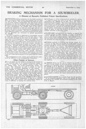
FFECTIVE braking mechanism for the trailer portion of 124 a six-wheeled tractor-trailer type machine has not been tcy) easy to devise. For one thing there has been the necessity to avoid, without complication, the risk of the relative movements of the two parts of the vehicle altering the position of the parts of the brake gear to an extent sufficient to cause derangement for another, there is the need to arrange the connections so that the brake gearand the twa parts of the vehicle can be simultaneously disconnected with as little trouble as possible. One way of surmounting these little difficulties appears to have been found by E. W. Rudd, and he describes his invention in patent specification No. 218,809.
The gear in question is applicable to six-wheeled vehicles in which the trailer is carried, at its fore end, upon a circu
lar turntable mounted an the frame of the tractor. The upper part of the turntable is recessed all round, the recesstaking the form of a V groove. The transmission means for the brake effort is an endless cable, which lies in this groove. The brakes are applied, in the usual manner, through the medium a shoes operating on drums on the rear wheels of the trailer. Another cable, provided with means of adjustment for its length, is attached at its ends to the levers of the brakes, and runs round a guide pulley which is mounted on a block carrying another such pulley round which runs the endless main operating cable already mentioned. Another block of the same kind is supported on the frame of the chassis whilst a third serves as a coupling means between the brake-operating gear on the tractor-and the endless'
cable. • The arrangement of the various parts will he best understood by reference to the accompanying illustration.
Other Patents of Interest.
IT is, of course, no new thing to arrange for the vacuum in
the induction pipe of an internal-combustion engine to operate a switch in the ignition circuit, so that, when the engine steps, the switch autothatically breaks the circuit. The advantage of such a system is thatit prevents the accidental discharge of the battery. A small .cylinder is connected to the interior of the induction pipe in such a Manner that, as the piston floating in the cylinder is sucked towards the end where suction is applied, it permits the closing of the switch contacts. Disconnection occurs when suction ceases, owing to the weight of the piston. For the switch of this type which he has patented in specification No, 218,828, J. G. P. Thomas claims that its detail construction is such as to eliminate troubles which have hitherto been encountered, largely because of difficulty in keeping the contacts clean. VALVE gear in which compressed air, instead of a spring, is used to return the valve to its seat is described in specification No. 209,035, by the Soc. Anon. des Ateliers d'Aviation Louis Breguet. The valve stem carries a piston, which moves in a cylinder made in one with the valve guide. Ports in the wall of the cylinder communicate with a source of compressed air, and the air within the cylinder is trapped by the piston, which closes the ports, so soon as the valve begins to open, so that the pressure of the air inside the cylinder increases as the valve opens.
CRANKCASES and gearboxes are usually, as regards the greater portion of them, castings. J. Fejes, in specification No. 205,508, describes a method of building them up of steel or other sheets, welded together. The methods of forming the joints and of building suitable bosses for studs into the structure are fully described in the specification.
SEVERAL methods of building the driving wheels of a
tractor, so that they can quickly be made useful for employment on eithtr road or land, are described in specification No. 214,233, by U.. Pavesi. The underlying principle is the same in each case, however, and will be understood if we make brief reference to only one of those methods. The -wheel is constructed, in the main, as for land oPeration, with steel rim and strakes. By its side is mounted a number of segments of a rubber-tyred rim, each segment being hinged to a pivot in the wheel. The segments are so designed that, when swung outwards round their pivots, they form a complete rim, rather larger in diameter than the steel rim of the wheel, and, locked in the outer position, they afford means of travel fur the wheel when the tractor is upon the highway.
A SIMPLE device, by the aid of which it is possible to know in any instant, in miles per gallon, the pctrol consumption of a travelling vehicle, is described ir specification No. 197,321, by E. F. Rowntree. It embodies two parts, one to measure the consumption in miles per gallon, the other to measure the speed in miles per hour. Both these measurements are calibrated on logarithmic scales, like those of a slide rule, and, by mounting the two scales side by side, they can be made to indicate the actual consumption in miles per gallon.
CALCIUM-CARBIDE as a source of gas for the operation of an internal-combustion unit is the subject of patent specifical.;on No. 210,727, the invention standing to the credit of R. J. Meyers.


