


Patents Completed.
Page 20
If you've noticed an error in this article please click here to report it so we can fix it.
Complete specifications of the following patents will he sent to any address in the United Kingdom upon receipt of eightpence per copy at the Sales Branch, Patent Office, Holborn, W.C.
CARBURETTER.— Thompson.— No. 15,945, dated 27th July, 1908.—This ut vention relates to carburetters of the type in which the supply of air and fuel is automatically adjusted, so that a ConStant proportion is supplied at all speeds
of the engine. The carburetter comprises a cylindrical outer casing, the upper portion of which is of slightly-reduced diameter and is screw-threaded to receive the induction pipe. Concentrically-mounted within the casing is a spray fuel nozzle, the cap of which is screwed into position so as to permit of a certain degree of adjustment and thus vary the area of the opening for the supply of fuel. Surrounding the fuel nozzle is a conical-shaped sleeve, to which is attached at its lower end a ring which has projecting lugs that engage slots provided in the casing. This sleeve is arranged to slide vertically in the carburetter under the action . of the suction produced by the engine. Attached to the wall of the sleeve is a wire which is slightly inblined and terminates at its upper end in a groove. The cap of the fuel nozzle has an arm which projects into the aforementioned slot and itself has a notch that engages the wire, lt will be seen that as the sleeve within the carburetter is raised by the suction of the engine the cap of the fuel nozzle will be rotated a greeter on less amount ac
cording to the degree lift of the sleeve, thus, as the speed of the engine increases, the air supply will also increase, so that the velocity of the air past the fuel nozzle will remain constant and at the same time the supply of fuel will be increased awing to the cap's being rotated, thereby increasing the area of the fuel nozzle. In this way a constant proportion of fuel and air is maintained at all speeds of the engine.
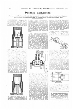
VALVE 31ECTIANTSINL—Saussard.-Nu. 2,537, dated 2nd February, 1909.— This invention relates to improved valve mechanism for controlling the admission and exhausting of the gases from the cylinder of an internal-combustion en. gine. The cylinder head is hollow, and it is divided into two chambers by a partition, so that one chamber is above the other. The upper chamber communicates with the carburetter and the lower chamber with the exhaust. An aperture is provided in the partition in which moves a sliding valve that is connected to a sleeve which extends through the top of the cylinder head and is pressed
upwardly by a spiral spring that is interposed between a collar carried by the sleeve and the top of the cylinder head. Within the sleeve is a spindle, which carries at its lower end two mushroom valves, one of which takes its seating on tot opening provided in the bottom of the cylinder head, and the other takes its seating on a hole or aperture in the bottom of the sliding valve. Both the sleeve carrying the sliding valve and the spindle carrying the two mushroom valves are operated by tappet levers receiving their motion from a single cam on the camshaft through the medium of a sliding spindle. During the compression and expansion strokes of the motor, the two mushroom valves are maintained closed by the action of the spiral spring. At the 'beginning of the exhaust stroke the tappet levers are caused to descend, thus opening the lower mushroom valve to allow the exhaust gases to escape. Upon further movement of the tappet lever the sleeve carrying the sliding valve will be forced downwardly against
the action of the spring, thus establishing communication between the carburetter and the cylinder, and, at the same time, cutting off communication between the exhaustand the cylinder. It will be seen that with this arrangement only cue of the valves communicates directly with the cylinder, and therefore there is less liability of leakage and consequently better compression is obtained.
MOTOR-DRIVEN AGRICULTURAL MACHINES.--Jeszenszky..—No. 28,429, dated 30th December, 1908.—According to this invention agricultural machines such as harrows, rollers, sowing and reaping machines are driven by light motorcycles. The two cycles are arranged side by side and coupled together by means of an adjustable bar. Attached to this bar and disposed between the motorcycles is the agricultural machine— a sowing machine being illustrated.
PETROL-ELECTRIC MOTOR VERICLE.—Stevens.—No. 20,210, dated 25th September, 1908.—This invention relates to an arrangement whereby existing omnibus chassis, in which the final drive is by means of sprocket wheels and chains from a differential gear fixed midway on the vehicle, may be driven by an electric motor. The electric motor is disposed between the two side members of the chassis and supported by two cross beams or brackets, so that its shaft is arranged longitudinally on the vehicle, thus permitting it to be coupled with the existing differential gear by means of the usual eardan shaft.