


Four-cylindered Two-stroke Engine
Page 66
If you've noticed an error in this article please click here to report it so we can fix it.
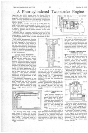
DATENT No. 695,737 comes from the General Motors
Corporation, Detroit, Michigan; U.S.A., and discloses a design for a four-cylindered two-stroke • compression-ignition engine. Although the patent deals only with the water-cooling system, it nevertheless throws an interesting light on•American trends in design. • •' . Each. cylinder is provided with a set of air-inlet ports (1); these are fed with pre-compressed air from a blower, not shown. The blower feeds a manifold which consists mainly of spaces •2 between the cylinders. The exhaust ports (3) are three in number, and are located opposite the air inlets in each cylinder, The ports lead to a common manifold, a feature of .which is that water-cooled columns are provided in the path of the exhaust gases. A camshaft 4) is used only for the purpose Of working the injector valves (5); these are reached by pushrods and rockers.
The cooling, arrangements forming the subject of the patent are illustrated by other drawings in the specification. The basic principle of the scheme is that the water Stream is directed at a high velocity towards the hottest points, whilst the other parts of the engine are cooled by slower-moving streams. A Cooling radiator for the lubricating oil is also incorporated.
BETTER PILOT INJECTION
PATENT No. 695,794 (A. Mueller and Leyland Motors Ltd., Suffolk House, Laurence . Pountney Hill, London, E.C.4), gives some interesting .views on the practice of pilot injection. Whilst admitting that the .principle is desirable, the patent states that Owing to the Momentary nature Of the pant charge, it is quite possible for it to be absorbed by the resilience of the piping, and at high speeds i.t can practically disappear. The patent describes a scheme for ensuring that the charge compressed in the pump does, in fact, appear at-the nozzle.
The difficulty is surmounted by providing two injection pumps, one for the pilot injection and one for the main charge, each pump being separately piped to the injector. Although this at first sounds rather expensive, in actual . fact a single pump performs both duties.
• The drawing shows such a pump; each plunger is made with a smalldiameter end (1) for the pilot injection, and a larger part (2) to deed with the main charge. Each unit . leads to a separate outlet (3 and 4) and two pipes lead to the injector.
A40 •
At the injector end of each pipe, a one-way •valve is fitted. Although the two plungers work in a single sleeve, they are actually separate members, being joined by a semi-universal .coupling (5). 'The object of this feature is to ease the manufacturing tolerances.
• An additional advantage is that by suitably arranging the cut-off edges of :the two plungers, any desired ratio can be obtained between the , two fuel charges,' in respect of both quantity and timing.
A MEAT-TRANSPORTING BODY
T"hygienic transport of meat is the object of a special body shown in patent No. 695,454 (1-1. Hodgson, 78 Leader Road, Sheffield, 6). With the body described, it is unnecessary for a person to enter it, thus enabling the floor to be kept perfectly Clean,
The drawing shows a side section of the body, which is fitted with an overhead chain conveyor (1). Numerous cross-members (2) are mounted on the conveyor and carry hooks to receive the carcases. A chain drive descends to a -low level where a shaft (a) is provided with •a winding handle. As shown, large carcases, such beef, could be carried on the lower r• of hooks only, but if constructed : smaller ones such as lamb, the und side of the conveyor would be loca at a much lower level, so that carca could then be hung from both runs. roll-up shutter (4) forms a closure the rear.
A VARIABLE-REDUCTION STEERING GEAR
THE usual type of worm-and-sec steering gear gives a constant red tion, and many variants have bs proposed to make the reducti variable, usually in the direction giving a lower gear as the wheels lc over. A scheme in which the ratio be varied to any designed extent shown in patent No. 695,701 Cochrane, 1543 Gladstone. Aven Windsor, Ontario, Canada).
Referring to the drawing, the ste ing column (1) is screwed and revol inside a cylindrical nut (2). The los side of the nut is cut into teeth ( although these are curved, they , essentially rack teeth and mesh with teeth on the sector (4).
When the column is turned, the slides up or down, rotation being g vented by a pin (5) engaging in a s in the nut. If this slot be straight, device would give a constant ratio, I in this case it is slightly S-shaped.
The result is that the nut is alloy to turn slightly as it revolves Iowa full lock, which means that the effect ratio is lowered at both Ads of movement. The patent covers the • of a ball-bearing thread . betwi column and nut.