


A Bt LRS AHEAD 3 TIME
Page 46
Page 47

Page 48
Page 49
If you've noticed an error in this article please click here to report it so we can fix it.
ew Midland "Red" 44-seat Single,ck Bus Weighs Under 5 tons and 'corporates Many Novelties, Including ubber Springing All Round, Independent
Front Suspension and Disc Brakes
BY producing ... 44-seat underfloor-engined singledeck bus, of integral construction, using a steel underframe, with an unladen dry weight of 4 tons 19 cwt., the Birmingham and Midland Motor Omnibus Co., Ltd., have set a standard which will undoubtedly influence bus design throughout the world. The use of the Metalastik toggle-link rubber suspension at the rear, independent wishbone suspension based on Metalastik rubber elements at the front, and of Girling disc brakes on both axles, not only represents a revolutionary combination of suspension and braking units in functional characteristics, but contributes to the low, unladen weight.
Two prototype vehicles have been completed, one of which is equipped with the latest version of the Hobbs gearbox having automatic gear selection. This box is also fitted with an over-riding hand control. The second vehicle has a conventional four-speed gearbox which will be the type to be fitted to the majority of the production vehicles.
These new models, type number S.14, are the first of a batch of .270 of similar design. The overall box dimensions are 8 ft. by 30 ft., and normal bus comfort is provided without concessions to austerity, the seats, which weigh 25 lb. each, being of the standard Midland " Red " pattern.
The vehicle has a 17-ft. 6-in, wheelbase, the front overhang being 5 ft. 5i in., and that at the rear 6 ft. 111 in. With a full, seated load of 44 passengers plus driver and conductor, the rear-axle loading is about 4 tons 1 cwt. out of a total laden weight of 8 tons. The tyres are of 9.00-in. by 20-in. section, and whilst it is intended to use single rear wheels, provision is made for twins. The turning circle is 65 ft.
A Metalastik toggle-link rear suspension system, the prototype of which was fully described in The Commercial Motor, on November 11, 1949, has been tested in service for 153,000 miles in a vehicle having a standard type of chassis. The front suspension, employing rubber as the spring medium, is entirely new, but B.M.M.O., have had considerable experience with independent front suspension systems in service vehicles. Although operating on entirely different principles, the front and rear suspension systems provide characteristics of substantially constant-periodicity form, and have the advan c8 tage over conventional systems in respect of ridin qualities, maintenance and low weight.
The Girling disc brakes have also been tested i service, and although further modifications May t introduced to reduce weight and aid maintenanc, operational results have been highly satisfactory. T1S.14 prototype is fitted with a hand-operated transmi: sion disc brake of a type which Would be suitable lc service use were the necessary revision of the law intn( duced, and in anticipation of this B.M.M.O. are desirm of obtaining experience with this type of brake. The fat brakes are hydraulically actuated with assistance frot a Lockheed continuous-flow pump driven from the gea box mainshaft. The power unit is an 8-litre direct-injection engine, designed and built by B.M.M.O. It has a bore of 4.45 in. and a stroke of 5.25 in. The unit develops 100 b.h.p. at 1,750 r.p.m., and 350 lb-ft. torque at 1,100 r.p.m. It is designed for integral construction with the gearbox and has characteristics and a power output identical with the engines fitted to the Midland " Red " S-type single-deck vehicle. From the gearbox the drive is transmitted by an open propeller shaft having Hardy Spicer joints, to a Kirkstall hypoid final drive of 4.44 to 1 ratio. The axle shafts are fully floating.
The main assembly of the underframe comprises a front, centre and rear structure for mounting the front suspension units, the engine and gearbox, t.nd the rear-suspension supports respectively, the cross-bearers being riveted to angle-section crib rails. The body sides have a stressed inner skin formed of light-alloy panels, which extend to the window panes, and the structure is stressed to cant-rail level.
At the front, longitudinal channel members are combined with deep prefabricated crossbearers of angle-section runners and struts, and the centre structure is a simple layout of longitudinal channels with end cross-members of similar section. All the rear-section main members are of the strutted-girder type, which form a monocoque structure with support members extending to the crib rails from the four corners of a rectangular frame assembly. The channel-section cross-members lit into the cribrail angles without change of section, and the girders are tapered at their ends to the same depth.
Whilst the centre and rear assemblies give a flat frame line, the front longitudinals are ramped by 2 in. to reduce the entrance height. From the ground to the first step is 1 ft. 01 in., and the risers are 11 las in. and 11 in. respectively. The entrance is 2 ft. 4 in. wide, and the height of the saloon floor,. 3 ft. 1 in.
The channel-section members and the girder sections are made of 1-in, steel, and the fabricated top-hat and square-section main pillars and the channel-section intermediate pillars are of 18-gauge steel. The stressed lightalloy skin is of 18-gauge material and the outer panels are in 19-gauge alloy. Solid rivets are employed for the inner skin where the stresses are high, and pop rivets in the more lightly stressed areas, including the outer panels.
The prefabricated girders are of welded construction, and welding is also used at some of the main joints of the frame members and at the attachment points of the gusset plates where a reduction in strength, without after treatment, can be allowed.. Crib-rail attachment to the frame members is by riveting.
Dimensional details of the frame sections give some indication of how weight has been reduced. For example, the front longitudinal channels and channel cross-members are 41-in. by 2-in. section and On, thick, the centre longitudinals being reduced in depth to 41 in. to fit into the cross-members; the girders are constructed throughout of 2-in. by 2-in. angle. These girders are 10 in. deep and the front longitudinals have an underslung angle-member of the same section to provide a mounting depth of 18 in. for the suspension brackets. Transverse rigidity in the plane of the suspension is provided by a channel,section bearer at the top and a box-section member at the bottom.
Additional strength is given by box-section brackets which form the struts between the longitudinals and the front upswept ends of the underslung angles, and act as the supports for the pivots of the torque-reaction arms. The off-side bracket is used for mounting the. steering box and panels. The lower crib angles are continued over the wheel-arches, and external bracing members of angle section are used to reinforce the skin in place of the top angles.
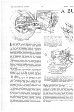
The front suspension is one of the features of greatest original interest, in that each wheel is. independently sprung and rubber is emplbyed as the spring medium.
c10 Each spring comprises a series of bonded rubber-tc metal sandwiches supported in their middle by a hinge plate with a fulcrum point in the upper wishbor assembly. The spring is assembled with its axis incline approximately 16 degrees above the horizontal whe laden and is located. endwise by the stub-axle standar and the main structure. .
The upper wishbone arm is approximately half tt length of the lower arm and the rubber spring is locate so that the reaction loads pass through the axis of tt spring and the horizontal axis of the lower wishbon the upper wishbone being very lightly loaded. A forwaro mounted tie locates the wheels and suspension in a for' and-aft direction and controls brake torque.
Because of the central position of the engine, ti suspension torque-reaction arms are located in front the axle, the forward mounting of the brackets allowii arms 41 in. long to be used. This reduces geometric errors to a minimum, and the slight angular moveme of the various hinge points are accommodated by ti use of Metalastik Spherilastik bushes at all points exce the outer pivot of the lower wishbone where a Metalast ultra-duty bush is employed. The universal moveme is accommodated by the inner bush and by slight ben ing of the two plates which form the link.
An important design feature is that the bottom link continually in tension and the spring takes the great part of the load, thus enabling the weight of the lin to be reduced. It is claimed that the system will n lose its properties duringthe entire life of the vehic Prolonged full-scale rig tests have been made. T spring rate at the front suspension is 2 in. per ton, t total bump deflection being 5 in. Newton telescoi shock absorbers are used for damping.
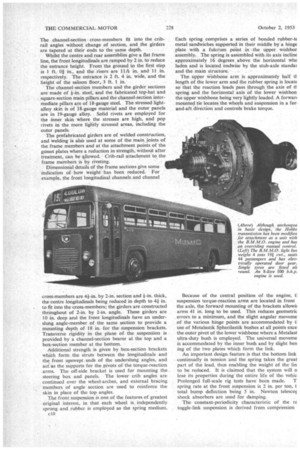
The constant-periodicity characteristic of the re toggle-link suspension is derived from compression e bushes supplementing the shear loads as the links e deflected from the horizontal_ or unladen position. le splay mounting of the links provides adequate sistance to torque, in addition to stiffness against celerating and braking forces and lateral loading. The ring rate at the rear is also 2 in. per ton, and the tal bump deflection 5 in., the laden weight on the .ck axle being li-times greater than the tare weight. Girling disc brakes fitted to the front wheels have liper units with three pairs of pads located at the pnt of the discs. It is probable that this type will be ed on successive vehicles. The experimental model is uipped with rear brakes having pads mounted at the p of the discs and operated by external cylinders rough bell-crank levers. It is anticipated that this will entually be the standard type to be adopted, combined th a single pad unit at the bottom of the disc for hand leration.
Transmission Disc Brake
The transmission-brake disc on the experimental bus ventilated by radial slots, and tests of this type,, of ic fitted to the wheels have shown adequate cooling. se pads of the transmission brake are operated by a .fling -wedge-action mechanism and bell-crank levers. External operating cylinders are used at the rear to Ince running temperatures under exceptionally favourable conditions. To make room for the external finders and air cooling, the discs are located inboard the wheels. The brake-load distribution is approxiitely equal On the two axles.
The Hobbs transthission is basically similar to the 3e described in The Commercial Motor on August 25, 50, using the improved version of the automatic con
trol unit, described on August 15, 1952. Operationally, the most important modification is the incorporation of an overriding control giving hand operation when required.
Changes on Full Throttle
The kick-down control is operated by a small pedal located in the normal clutch-pedal position. This contra increases the speed at 'which changes are made and enables the vehicle to be accelerated at the maximum rate through the gears with governor settings arranged to give normal gear changing. The overlapping engagement characteristic of the hydraulically operated clutches and brake-reaction members of the epicyclicgear assembly makes it possible for changes to he made on full throttle.
Bodywork details, the design of which contributes to weight reduction, include a Whitley triple-route destination indicator and an Auster divided windscreen. The side windows are Hallam, Sleigh and Cheston type, glazed With f-in. glass, and with the exception of the rear D-light, each incorporates twin sliding windows. The front-entrance doors are of the gliding type operated by a C.A.V. motor and Peters chain gear.
C.A.V. or Simms electrical equipment is used, and the B.T.H. speedometer is of the electric tachometer type; the dynamo unit is belt-driven from the gearbox.
Tests of the bus on the M.I.R.A. proving ground at Nuneaton are in progress and will be continued during the coming weeks. According to Mr. D. M. Sinclair, general manager of the company, the performance-of the suspension units and the rigidity of the frame structure during repeated runs over the pave, have provisionally justified the expectations of the design staff.