


An Ingenious Two-stroke Oil Engine
Page 54
If you've noticed an error in this article please click here to report it so we can fix it.
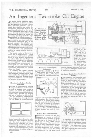
AN engine design possessing many novel features is shown in patent No. 452,2.40 by A. G. Michell, 4, Bank Place, Melbourne, Australia. This in-' venter first observes that whilst the auto-ignition temperature of an oil engine is usually reached by the use of a high-compression ratio, this is by no means the only possible method, and he proceeds to describe a scheme for pre-heating the charge so that a high compression is no longer necessary.
Referring' to the accompanying drawing, it will be seen that swash-plate construction is employed and, in the present, example, the cylinders are three in number. The general principles are orthodox, an air charge being introduced at the bottom of the stroke, via ports 2, whilst a cam-operated valve controls an exhaust outlet in the cylinder head.
The novelty resides in the use of a second row of inlet ports (1). These are connected with another cylinder earlier in cyclic sequence, and operate as follow: After the air charge has entered from ports 2 they are closed by the moving piston. By the time this has occurred, there enters through the second ports (1) a hot charge of exhaust gas from another cylinder, which increases the temperature and pressure of the new charge.
In addition, the patent contains many novel features, for example, a dash-pot spring abutment for the main shaft enables the compression to be adjustable, whilst the working pistons may be extended as at 3 to form pumping units for the air supply.
Manufacturing Gudgeon Pins by Press-work.
THE use of sheet metal for building components hitherto machined from the solid is making great strides in America, and patent No. 452,094 by E. C. Abbe, 43, Glenwood Circle, Longmeadow, Mass., describes how gudgeon pins may be produced by this method.
The first operation is the production of an elongated cup by deep-drawing. This cup, shown in the accompanying sketch, has a cylindrical exterior and a conical bore, being thickest at the blind end. The next operation consists of welding two of these cups end to end, pressure being used to unite the sur'faces while they are heated. After this, a finish is produced by grinding, during which operation the central oil groove is also machined.
B44 A Brockhouse Trailer-coupling Refinement.
D ATENT No. 452,222 by J. Brock' house and Co., Ltd., and A. T. Dear, both of Victoria Works, West Bromwich, deals with a modification of the
company's well-known quick-detachable trailer coupling. The object of the improvement is to enable slack between the ball joint and the housing to be taken up and, to this end, it is proposed to extend the housing in the shape of a lug (I) which is split and clamped by a setscrew. Thus, suitable adjustment is easily obtained and rattle is eliminated.
A Dyson Road-rail Combination. DESIGNED primarily for the bulk transport of liquids, a road-rail transport scheme is described in patent No. 451,624 by J. Dyson and R. A. Dyson and Co., Ltd., 76-80, Grafton Street, Liverpool. The system embraces the use of a semi-trailer that can be hauled to the railhead by a tractor, and there transferred to a specially constructed railway wagon. The trailer has, in addition to the usual tyred
wheels,, two exter nal pairs (1) of smaller diameter. These rest on a pair of rails fixed on the wagon an& by this means, the trailer is lifted clear of the floor. A cross-member (2) projects over the rails, and a pair of jacks (3) performs the dual function of adjusting the height and lifting the tanker clear of the tractor turntable. / 451624 / The Latest Daimler-Benz Combustion System.
aUCH research into oil-engine corn1V1 bustion systems has been undertaken by Daimler-Benz A.G., Stuttgart, Germany, and the company's latest developments in this direction are disclosed in patent No. 452,005. The salient points are a combustion chamber (3) in the piston crown, in conjunction with an air cell (1). The fuel is injected down the passage 4 in a direction towards the depression in the piston. The air cell is joined to the combustion space by a pair of conical bores (2), one on each side of the fuel stream.