


A FLEXIBLE MOUNTING FOR FLYWHEELS.
Page 30
If you've noticed an error in this article please click here to report it so we can fix it.
A Résumé of Recently Published Patent Specifications.
T"name S. F. Edge; although so well known in the motor world, does not (Atmu appear in the lists of patents. This time, however, it is coupled with that of Sydney Smith in patent No. 295,959.
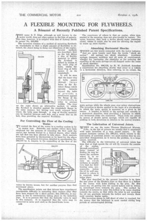
The invention consists of .a method of mounting flywheels on crankshafts so that a slight amount of flexibility is obtained, the object being to damp out vibrations of the engine. Several methods are described ; that on the left shOws a disc of flexible material to which the flywheel is bolted by means of the 'outer sing of bolts, whilst the inner ring of bolts secure it to its crankshaft.
It will be seen that the inner ring of bolts passes through large holes in the flywheel flange which extends inwards beyond the bolts to provide a steadyment against the flange of the or in order to prevent wobble. The view on the right shows an alternative method, in which the flywheel is steadied against the crankshaft flange in the same manner, but having very much enlarged holes where the bolts pass through. A ring of flexible material can be inserted between each hole and a metal disc on its bolt, thus providing the required flexibility.
For Controlling the Flow, of the Cooling TO control the flow of the water in a cooling system is by
no means new. Butterfly and similar valves have bean employed for the purpose of retarding the flow until the engine has become heated to a desired degree, after which the full flow has been allowed to take place. Such controls have been actuated by thermostats or by hand for the above purpose. The present invention, detailed in specification No. 292,177 by A. Angers, is the controlling of the flow of the water by known means, but for anther purpose than that mentioned above.
The specification points out that drivers have experienced considerable difficulty in restarting their engines after they have been stopped for a short period; this difficulty, it suggests, is due to condensation taking place in the induction pipe. It is to prevent this that the butterfly valve is used in this instance. It is suggested that the valve may be connected to some part such as the hand-brake lever.
B46
The -experience of others is that an engine, when once started in the morning, does not give trouble to restart. We agree, however, that such a device should make restarting easier, whilst it might also be used for allowing the engine to warm up more rapidly.
Absorbing Horizontal Shocks.
THERE are few words connected with the motor industry
that are more loosely used than the words "shock absorber." All springs are shock absorbers. Auxiliary springs, dampers, snubbers and all sorts of contrivances, whether for increasiug the elasticity or for reducing the elastteity of the main springs are all dumped under the name of shock absorber.
Specification No. 29G,I28, by H. W. Ionkhoff, describes a contrivance for absorbing shocks that occur to a vehicle in a horizontal direction, thus relieving, to an extent, the
main springs while the wheels pass over minor obstructions. The invention is shown applied to the bogie of a six-wheeler, in which the main spring is mounted on a pivot in its centre. A bracket is bolted to the springs and extends in a downward direction, thus providing a fulcrum to which two horizontal links are connected. These links are joined by means, of double spiral springs, which are capable of yielding in both directions in relation to the central bracket, The Lubrication of Universal Joints.
WHEN we see the name Thomas Blackwood Murray, D.Sc., in the list of patents we usually find it associated
with some invention of a very sound nature. In the present instance—patent No. 296,211, which relates to the lubrication of universal joints --we must confess that we are somewhat disappointed, as it leaves the problem, to a large extent, unsolved.
The difficulty in the lubrication of universal joints has been that at high speeds the oil will fly towards the outside of the easing, through centrifugal force, instead of finding its way between the surfaces where it is required. The 'pressure on such surfaces is usually very high for their bearing area, consequently, unless the oil be well conducted to where it is required, wear takes place.
The plan described in the present invention is to form the star piece of the Hooke's joint so that there is a hollow in the centre with holes leading to the pins. By this means any oil getting into the central hollow will he driven by centrifugal force towards the pins. The method by which oil is induced to enter this hollow is by vanes slanting towards the centre, so that while the joint is not revolving the oil can gravitate towards the hollow and remain there until rotation begins again.
The invention seems to fall short of what is required, for the reason that the lubricant is most needed during long periods of uninterrupted driving.