


HINTS ON MAINTENANCE.
Page 30
If you've noticed an error in this article please click here to report it so we can fix it.
How to Get the Best Out of a Vehicle, to Secure Reliability and to Avoid Trouble
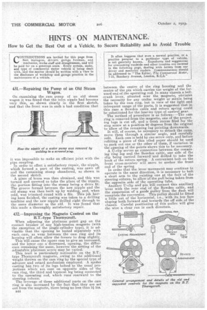
431.—Repairing the Pump of an Old Steam Wagon.
On examining the ram pump of an old steam wagon it was found that the inlet nipple had become very thin, as shown clearly in the first sketch, and that the front was in such a bad condition that
it was impossible to make an efficient joint with the pipe coupling.
In order to effect a satisfactory repair, the nipple, which formed a part of the casting, was sawn off and the remaining stump chamfered, as shown in the second sketch.
A piece of brass was then obtained, and this was turned and screwed to take the place of the nipple, the portion fitting into the stump being a drive fit. The groove formed between the new nipple and the old stump was then built up by welding, and, when cold, was trimmed round with a file. This job having been finished, the casting was taken to a drilling machine and the new nipple drilled right through to the same diameter as the old. It was found that this made a thoroughly satisfactory repair.
432.—Improving the Magneto Control on the B.T.-type Thornycroft.
When adjusting the platinum point gap on the contact breaker of any high-tension magneto (with the exception of the single-cylinder type), it is advisable that the opening be tested separately with each cam, as wear between the cam ring and its housing will often allow the former to drop slightly. This will cause the upper cam to give an increased, and the lower one a decreased, opening, the difference remaining the same, however the setting of the adjustable 'platinum screw may be varied.
This trait is particularly noticeable on the B.T.type Thornycroft magneto, owing to the additional -weight tlutiwn on the cam ring by the special type of advance and retard mechanism employed. A spider casting has tWo of its legs bolted to the usual projections which am cast on opposite sides of the cam ring, the third and topmost leg being connected to the operating rod, which runs rearward to the steering column.
The leverage of these additional parts on the cam ring is also increased by the fact that they are set out from the magneto, there being no less than 3i, ins.
B44
between the centre of the ring housing and the centre of the pin which carries the weight of the forward end of the operating rod. In many chassis a bellcrank lever, situated near the magneto, obviates the necessity far any undue weight or strain being taken by the cam ring, but in view of the light and infrequent usage of the parts, it is suggested that in this case a Bowden cable and return spring could be substituted for the heavier type of control gear. The method of procedure is as follows : —The cam ring is removed from the magneto, one of the projecting lugs is cut off, and a fresh recess filed for the stop screw at a position 90 degrees from the original to allow of the remaining lug pointing downwards. It will, of course, be necessary to detach the cams, move them through a similar angle, and carefully refit. Each cam is held by one screw only, and before -refitting a piece of thin oiled paper should be used to.pack out one or the other of them if variation in the opening of the points shows this -to be necessary. A IJ-clip serves as connection between the remaining "ring lug and the Bowden cable, one side of the clip being carried forward and drilled to take the hook of the return spring. A convenient bolt on the front cross-member will serve to anchor the front end of the spring..
In order that the lever movement may continue to operate in the same direction, it is necessary to bolt a short arm to the existing one at the foot of the steering column, to allow of the Dull being taken from the opposite side of the operating tube.
Another IT-clip and pin will connect this auxiliary lever with the rear end of the Bowden cable, and the suspension of a guide pulley from the dash will complete the conversion. This pulley Should be fitted a little out of the horizontal, i.e., with its top face sloping both forward and towards the off side of the chassis. Careful positioning of this pulley -will give the wire a clear run in each direction.