 1
1 2
2 3
3 4
4 5
5 6
6 7
7 8
8 9
9 10
10 11
11 12
12 13
13 14
14 15
15 16
16 17
17 18
18 19
19 20
20 21
21 22
22 23
23 24
24 25
25 26
26 27
27 28
28 29
29 30
30 31
31 32
32 33
33 34
34 35
35 36
36 37
37 38
38 39
39 40
40 41
41 42
42 43
43 44
44 45
45 46
46 47
47 48
48 49
49 50
50 51
51 52
52 53
53 54
54 55
55 56
56 57
57 58
58 59
59 60
60 61
61 62
62 63
63 64
64 65
65 66
66 67
67 68
68 69
69 70
70 71
71 72
72 73
73 74
74 75
75 76
76 77
77 78
78 79
79 80
80 81
81 82
82 83
83 84
84 85
85 86
86 87
87 88
88 89
89 90
90 91
91 92
92 93
93 94
94 95
95 96
96 97
97 98
98 99
99 100
100 101
101 102
102 103
103 104
104 105
105 106
106 107
107 108
108 109
109 110
110 111
111 112
112 113
113 114
114 115
115 116
116 117
117 118
118 119
119 120
120 121
121 122
122 123
123 124
124 125
125 126
126 127
127 128
128 129
129 130
130 131
131 132
132 133
133 134
134 135
135 136
136 137
137 138
138 139
139 140
140 141
141 142
142 143
143 144
144 145
145 146
146 147
147 148
148 149
149 150
150 151
151 152
152 153
153 154
154 DEMONSTRATIONS
Page 141
Page 142
If you've noticed an error in this article please click here to report it so we can fix it.
Bendix puts the pressure on
MI The first demonstration at this year's Workshop Conference and exhibition was given by Bendix on its Test Case. The case contains three pressure gauges reading up to 20 bar (290psi). Only one case is required to carry out a test, but for our demonstration three were used.
Delegates were reminded of the requirement to carry out an annual check of the air pressure drop across the loadsensing valve; the values required are stamped on the plate.
To begin the demonstration delegates were shown how easy it is to connect the gauge hoses onto the test points via couplings not unlike miniature versions of those used on trailers. The more detailed parts of the demonstrations were filmed by a television camera crew and shown on large monitors to enable delegates to follow the procedures more closely.
Pressure differentials clear
Having made all the necessary connections the test procedure was briefly talked through checking braking pressures on the front service circuit, rear service and secondary, anti-compounding valve and the inlet and outlet side of the loadsensing valve.
Not only were these readings easily seen but the pressure differentials were also clear. Pressure on the input side of the load-sensing valve could be seen to be three bar while on the output side pressure was reduced to 11/4 bar. Pressure in the front and rear braking circuits (tested upstream of the load-sensing valve) must be equal — again the readings were obvious.
Adapters are also available to connect onto the suzie couplings thus checking that the required six bar is being delivered to the trailer. Having completed the demonstration, all three test cases were disconnected in a matter of seconds.
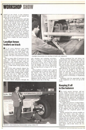
Hope's connections
• John Hope started the demonstration of the Hope Scrutineer by wheeling it up to a semi-trailer and quickly making the necessary connections. The demonstration unit was mounted on a trolly (but can be mounted in other ways) along with two batteries, and a compressed air cylinder was secured to it. In this form the Scrutineer is fully self-contained and, as demonstrated, can perform all the checks on a trailer without the aid of a tractive unit.
Before demonstrating its functions, Hope gave a brief description of the unit's controls, history and development. First to be checked was the trailer's lights. By switching to each circuit in turn the left and righthand indicators, side and brake lights and the high-intensity rear fog-lamps were all checked. The television monitors showed a close-up of the unit's meter indicating how many bulbs were operating on each circuit. A deliberate fault was caused on one circuit, so that delegates were able to see how such defects are shown up on the Scrutineer.
Moving on to the air system, each line can be separately activated and held under pressure with the air locked inside. As an air leak had already been created, the monitors were able to show the relevant gauge dropping back as the pressure declined and in the absence of a running tractive unit, the leak was also audible.
Finally, delegates were able to watch as the brakes were activated via the Scrutineer's remote control. Hope explained, this is useful to check the amount of free travel in the brake chambers and to check that all have roughly the same amount of travel.
Lasalign keeps trailers on track
• If, for every kilometre your trailer travelled forwards it was dragged 2.5 metres sideways, you would not be surprised if the tyres wore out quickly. This was the message from Derek Godden of Lasalign, who gave demonstration number two.
With so many miles of motorway in use today, high mileages from tyres can be achieved — but not if trailer axles are misaligned. Fuel consumption also suffers. These points were demonstrated by the use of a small model being pushed along the floor.
With all the axles properly aligned the model ran freely, then both trailer axles were set towards the left and the model ran with the trailer crabbing badly. Finally, the axles were set to "fight" each other and, while the trailer ran in line, the increased friction caused the model to slow down and stop very quickly.
Godden talked delegates through the
axle checking and realigning procedure. First a "trapeze" is hung from the front axle of the trailer — the lower bar acting as the laser's mount. Next a "flag" is hung from the kingpin. The laser is then shone onto the kingpin and moved downwards and the flag moved to hang at 900 to the axle.
Next, Godden's assistant used a special centre-finding bar to indicate the middle of the chassis. The laser was then moved along the trapeze until the beam struck the centre indicator. The beam was again aimed at the flag. Any error in the axle's alignment will be shown by the laser missing the centre line of the flag. Having misaligned the axle before the demonstration, the delegates were able to watch as the axle was brought back into line and the laser beam moved onto the flag's centre line. The axle's adjusting link was then securely locked in that position.
Having set the front axle to point in the right direction, the second and third axles are set to be parallel to the first. To check the precise distance between the axles on each side a special measuring caliper is used. Adjustment is done by the same method of shortening or lengthening the link.
Delegates took the opportunity to look at the equipment as it was set up on the trailer.
Keeping it all in the balance
• As truck speeds increase, and upsprung weight decreases and more responsive steering systems are introduced, there is a greater need to balance wheels. Michelin took the opportunity provided by the Workshop Conference and Exhibition to demonstrate the balancing of commercial vehicle wheels.
To explain the process of wheel balancing, a Balco 92 unit was used. This unit is portable and runs off a mains rechargeable battery. The wheel was already mounted on the balancer and was spun by a hand crank until the required speed was reached.
Having attached the relevant weights to balance the wheel, some time was devoted to answering questions. Delegates asked what were the results of prolonged running with out-of-balance wheels. These ranged from flat spots on the tyres when the out-of-balance forces were on the circumference, to wear in the steering linkages where side-to-side forces are encountered.