


America Develops Petrol Injection
Page 54
Page 55
If you've noticed an error in this article please click here to report it so we can fix it.
Simplicity in Design and • Ease of Production Are Features of the 'Bosch Petrol infection System
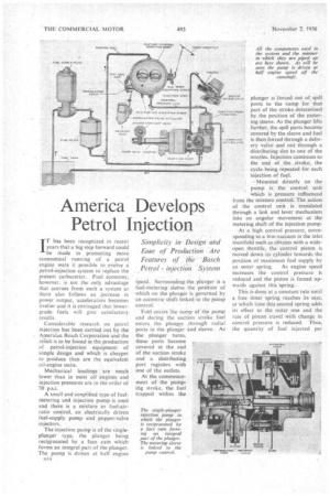
IT has been recognized in recent years that a big step forward could be made in promoting more economical running of a petrol engine were it possible to evolve a petrol-injection system to replace the present carburetter. Fuel economy, however, is not the only advantage that accrues from such a system as there also follows an increase in power output, acceleration becomes livelier and it is envisaged that lowergrade fuels will give satisfactory results.
Considerable research on petrol injection has been carried out by the American Bosch Corporation and the re..s.ult is to be found in the production of petrol-injection equipment of simple design and which is cheaper to produce than are the equivalent oil-engine units.
Mechanical loadings are much lower than in most oil engines and injection pressures are in the order of 70 p.s.i.
A small and simplified type of fuelmetering and injection pump is used and there is a mixture or fuel-airratio control, an electrically driven fuel-supply pump and poppet-valve injectors.
The injection pump is of the singleplunger type, the plunger being reciprocated by a face cam which forms an integral part of the plunger. The pump is driven at half engine o14
.4peed. Surrounding. The plunger is a fuel-metering sleeve the position of which on the plunger is governed by
an eccentric shaft linked to the Pump control:
Fuel enters the sunip of. the pump
and during the suction stroke fuel enters the plunger through radial ports in the plunger and sleeve. As the plunger turns, these ports become covered at the end of the suction stroke and a distributing port registers with one of the outlets.
At the commencement of the pumpifig stroke, the fuel trapped within the plunger is forced out of spill ports to the sump for that part of the stroke determined by the position of the metering sleeve. As the plunger lifts farther, the spill ports become covered by the sleeve and fuel is then forced through a delivery valve and out through a distributing slot to one of the nozzles. Injection continues to the end of the stroke, the cycle being repeated for each injection of fuel.
• Mounted directly on the pump is the control unit Which is pressure influenced from the mixture control. The action of the control unit is translated through a link and lever mechanism into an angular movement at the metering shaft of the injection pump.
At a high control pressure, corresponding to a low-vacuum in the inlet . manifold such as obtains with a wideopen throttle, the control piston is moved down its cylinder towards the position or maximum fuel supply by an outer spring. As engine speed increases the control pressure is reduced and the piston is forced upwards against this spring..
This is done at a constant rate until a free inner spring reaches its seat, at which time this second spring adds its effect to the outer one and the rate of piston travel with change in control pressure is reduced. Thus, the quantity of fuel injected per
stroke of the plunger is a function of the control pressure applied to the piston.
During deceleration, full or partial cut-off of the fuel to eliminate waste can be automatically accomplished. One method, which is not illustrated, is to use an auxiliary piston carried within the control piston and biased by a low-rate spring.
During normal operation from idle to full throttle, this auxiliary piston moves with the control piston as a unit. On decelerating, the piston moves upward within the control piston and the injection pump metering lever is moved to the cut-off position.
In its simplest form, the mixture control is . a manifold pressure control and throttle body, having a chamber which passes on a modified manifold pressure to the injectionpump control during cold starting and idling.
For reasons of clarity, the throttle plates are not shown in the sectional view of the mixture control. They are, however, of a conventional type having an idling port arranged just above the closed throttle position. This port is connected to a passage which enters a control chamber formed in the throttle body. This chamber, in turn, connects with the injection-pump control.
Air flow at idling speed is adjusted by a screw in the usual manner whilst the fuel-air mixture is adjusted by a second screw. The latter controls the flow of air through a slot and has the effect of modifying the control-chamber pressure. Above the idle setting, the edge of the throttle rises above the idle port which is then under manifold pressure and the idle-mixture adjusting screw has no effect on the fuelair mixture.
To obtain excess fuel for starting, the control pressure is raised by adjusting a warm-up valve which operates within a passage between the upper (atmospheric) and lower (intake manifold) pressures. This valve, which is connected via a pin and an eccentric shaft to a lever which also carries a fast-idle cam, is operated by a modulating-valve
actuator controlled by the heat of the exhaust.
During normal running, the warmup valve is seated in such a position that the pressure in the chamber equals that of the intake manifold. Under cold operating conditions the valve assumes a position where it modifies the manifold pressure to the pump control. This position is shown in the illustration. The injection pump delivers additional warm-up fuel to the engine until the valve reaches the normal-operation position.
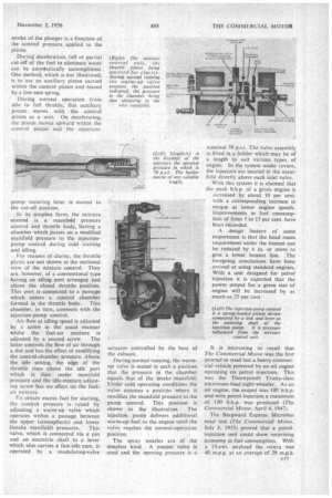
The spray nozzles are of the simplest kind. A poppet valve is used and the Opening pressure is a
nominal 70 p.s.i. The valve assembly is fitted in a holder which may be of a length to suit various types of engine. In the system under review, the injectors are located in the manifold directly above each inlet valve.
With this system it is claimed that the peak b.h.p. of a given engine is increased by about 10 per cent.
with a corresponding increase in torque at lower engine speeds.
Improvements in fuel consump
tion of from 5 to-15 per cent. have been recorded.
A design feature of some importance is that the head room requirement under the bonnet can be reduced by 6 in. or more to give a lower bonnet line. The foregoing conclusions have been arrived at using standard engines. With a unit designed for petrol injection it is expected that the power output for a given size of engine will be increased by as much as 25 per cent.
It is interesting to recall that The Commercial Motor was the first journal to road test a heavy commercial vehicle powered by an oil engine operating on petrol injection. This was the Thornycroft Trusty-class maximum-load eight-wheeler. As an oil engine, the output was 100 b.h.p. and with petrol injection a maximum of 150 b.h.p. was produced (The Commercial Motor, April 4, 1947).
The Borgward Express Microbus road test (The Commercial Motor, July 8. 1955) proved that a petrolinjection unit could show surprising economy in fuel consumption. With a 15-cwt. payload the return was 40 m.p.g. at an average of 29 m.p.h.