


Hydraulic Operation for Clutches
Page 23
If you've noticed an error in this article please click here to report it so we can fix it.
To operate a cluteli by hydraulic 1 means if the object of a ,theme ohown in patent No. 571,432, by F. Tarlton, 13, Grange Road: Alvaston, Derby. The chief feature of the.
arrangement is the means adopted for nullifying any slight inaccuracies of alignment between the hydraulic mechanism and the thrust-ring of the clutch.
The drawing shows, diagrammatically, the general layout, which comprises a pedal-operated cylinder piped to a multiple cylinder block (1) containing a number of pistons which apply the force to the thrust-ring (2). Three equi-spaced pistons are employed, and, in action, they all exert equal force; if facial misalignment be present it means that one or more may have a different distance to traybl, but once in contact, -all three become perfectly compensated. The specification shows, in addition to the accompanying diagram, more precise details of the actual construction.
A TWO-WHEELED AGRICULTURAL DRIVING BOGIE
ASMALL agricultural driving unit, having two in-line wheels, forms the subject of patent No. 571,347. which comes from W. Henderson, and Aveling Barford, Ltd., " Invicta " Works, Grantham, Lincs. The machine is intended to be steered by an operative walking behind it, who tilts it on to one wheel when cornering.
The scheme isdistinctly novel; because, although the bogie performs the tractive efforts for an attached implement, it does notcarry its engine, this being fixed to the implement. In -the drawing, a pivot (1) forms the point of attachment to 'the implement, and about the same centre revolves a sprocket wheel (2), which receives the drive from the engine. A further chain (3) drives one of the wheels, the other wheel being driven by an endless track surrounding pneumatic tyres. 'Wheel it is desired to steer, the rocking pivot is temporarily locked by a pin (4), an action Which enables the driver to lift one wheel clear of the ground by pressing down on a handlebar.
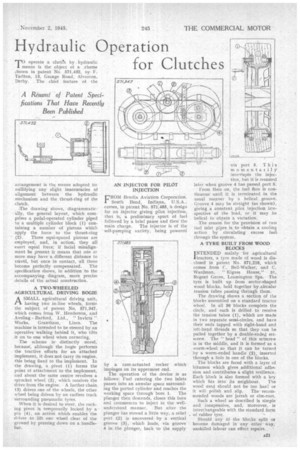
CROM Bendix Aviation Corporation,
South Bend, Indiana, U.S.A., comes, in patent No. 571,485, h design for an injector .giving pilot injection, that is, a preliminary spurt of fuel followed by a brief pause and thenthe
main charge. The injector is of the self-pumping vari'efy, being powered by a cam-actuated rocker which impinges on its uppermost end.
The operation of the device is as follows; Fuel entering the two inlets passes into an annular space surrounding the ported cylinder and reaches the working space through bore 1. The plunger then descends, closes this bore and commences to inject in the wellunderstood manner, But after the plunger has moved a little way, a relief port (2) is uncovered by a vertical groove (3), which leads, via groove 4 in the plunger, back •to the supply
via port 5. This momentarilyinterrupts the injection, but it is resumed later when groove 4 has passed port S.
From then on, the fuel flow is continuous until it is terminated in the usual manner by a helical groove. Groove 4 may be straight (as shown), giving a constant pilot injection irrespective of the load, or it may be helical to obtain a variation.
The reason for the provision of two fuel irate 'pipes is to obtain a cOoling action by circulating excess fuelthrough the system.
. A TYRE BUILT FROM WOOD
INTENDED mainly .for agricultural ltractors, a tyre made of wood is disclosed in patent No. 571,216, which comes from C. Bell-Walker, and C. Wardman, " Migass House," 31, Regent Grove, Leamington Spa. The tyre is built up from sector-shaped wood blocks, held together by .icircular tension tubes passing through them.
The drawing shows a section of the blocks assembled on a standard tractor wheel. In all 30 blocks complete the circle, and each is drilled to receive the tension tubes -(1), which are made in two 'separate semi-circles, and have their ends tapped with right-hand and teft-hand threads so that they can be pulled together by a double-:ended setscrew. The " head " of this setscrew is in the middle, and it is formed as a. worm-wheel so that it can be turned by a worm-ended handle (2), inserted through a hole in one of the blocks.
The blocks are faced with a layer of bitumen which gives additional adhesion and contributes a slight resilience. Each block is also formed with a key which fi-ts into its neighbour. The wood used should not be too hard or
it will polish and slip. The recommended woods are jarrah or elm-root.
Such a wheel as described is simple aud inexpensive, and, moreover, is interchangeable with the standard form of rubber tyre.
Should any of the blocks split or become dainaged in any" other Way, unskilled labour can effect repairs.