


A Novel Injection Pump
Page 66
If you've noticed an error in this article please click here to report it so we can fix it.
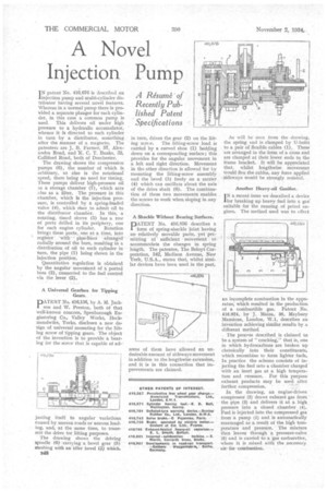
I N patent No. 416,676 is described an injection pump and multi-cylinder distributor having several novel features. Whereas in a normal pump there is provided a separate plunger for each cylinder, in this case a common pump is used. This delivers oil under high pressure to a hydraulic accumulator, whence it is directed to each cylinder in turn by a. distributor, something after the manner of a magneto. The patentees are 1. B. Farmer, 57, Alexandra Road, and K. C. T. Banks, 32, Cuffiford Road, both of Dorchester.
The drawing shows the compression pumps (6), the number of which is arbitrary, as also is the rotational speed, there being no need for timing. These pumps deliver high-pressure oil to a storage chamber (7), which acts also as a filter. The pressure in this chamber, which is the injection pressure, is controlled by a spring-loaded valve (4), which rises to admit oil to the distributor chamber. In this, a rotating, timed sleeve (5) has a row of ports drilled in its periphery, one
for each engine cylinder. Rotation brings these ports, .one at a time, into register. with afranged radially around the bore, resulting in a distribution of oil to each cylinder in turn, the pipe (I) being shown in the injection position.
Quantitative regulation is obtained by the angular movereent of a ported boss (3), connected to the fuel control via the lever (2).
A Universal Gearbox for Tipping
• Gears.
PATF-NT No. 416,136, by A. M. Jackson and W. Preston, both of that well-known concern, Spenborough Engineering Co., Valley Works, Heckmondwike, Yorks, discloses a new design of universal mounting for the lifting screw of tipping gears. The object of the invention is to provide a bearing for the screw that is capable of ad
jutting itself to angular variations caused by uneven roads or uneven loading, and, at the same time, to transmit•the drive for lifting purposes.
The drawing shows the driving spindle (6) carrying a bevel gear (5)meshing with an idler bevel (3) which,
B48 in turn, drives the gear (2) on the lift ing screw. The lifting-screw load is carried by a curved shoe (I) bedding down on a corresponding surface ; this provides for the angular movement in a left and right direction. Movement in the other direction is allowed for by mounting the lifting-screw assembly and the bevel (8) freely on a carrier (4) which can oscillate about the axis of the drive shaft (6). The combination of these two movements enables the screws to work when sloping in any direction.
A Shackle Without Bearing Surfaces, DATENT No. 416,856 describes a 1 form of spring-shackle joint having no relatively movable parts, yet permitting of sufficient movement to accommodate the changes in spring length. The patentee, The Beloyt Corporation, 342, Madison Avenue, New York, U.S.A., states that, whilst similar devices have been used in the past, some of them have allowed an undesirable amount of sideways movement in addition to the lengthwise extension, and it is in this connection that Incpnavements are claimed.
As will be seen from the drawing, the spring end is clamped by U-bolts to a pair of flexible cables (1).. These are arranged in the form of a cross and are clamped at their lower ends to the frame bracket. It will be appreciated that, whilst. lengthwise. movement Would,flex the cables, any force applied sideways would be strongly resisted,
Another Heavy-oil Gasifier, I N a recent issue we described a device for breaking up heavy fuel into a gas' suitable for the running of petrol engines. The method used was to effect an incomplete combustion in the apparatus, which resulted in the production
of a combustible gas. Patent No. 416,024, by J. Maim, 35, Maybury Mansions, London, W.1, describes an invention achieving sirnilar.results by a different method.
The procPss described is claimed to be a system of "cracking," that is, one in which hydrocarbons are broken up chemically into their constituents, which recombine to form lighter fuels.
In practice the scheme consists of in jecting the fuel into a chamber charged with an inert_ gas at a high tempera ture and pressure. For this purpose exhaust products may be used after further compression. • " In the drawing, an engine-driven compressor (2) draws exhaust gas frcini " the pipe (3) and delivers it at a high pressure into a closed chamber (4). Fuel is injected into the compressed gas from a pump (1) and is automatically rearranged as a result of the high temperature and pressure. " The mixture then leaves through a pressure-valve (5) and is carried to a gas carburetter, where it is mixed with the necessary air for combustion.