


A NEW GILFORD
Page 50

Page 51
Page 52

If you've noticed an error in this article please click here to report it so we can fix it.
Perkins-engined 4-tonner
THE 1935 range of goods and passenger vehicles made by the Gilford Motor Co., Ltd., Brentside Works, North Circular Road, Park Royal, London. N.W.10, will include a Perkins-engined 4-tonner of entirely new design, whilst the Hera 32-seater will be available with the latest Dorman six-cylindered oil engine. Full particulars of the complete range will be announced later, but the first-named is now practically ready for production, and we were recently afforded an opportunity of thoroughly examining the chassis, which is of considerable interest.
Its light weight is specially noteworthy. Complete with a 13-cwt. body and cab, the vehicle weighs under three tons, the chassis alone turning the scale at 2 tons 7 cwt. In view of the fact that this includes an oil engine, the figure is certainly most creditable. Weight-saving appears to have been effected largely by simplicity in design and the avoidance of a multiplicity of small parts. There are no indications of strength having been sacrificed, or of equipment having been weight down to a low figure.
With regard to appearance, the frontal aspect is extremely pleasing. Good looks have for many years been a pronounced characteristic of the products of the Gifford factory, but in the latest model this quality is particularly marked, as can be appreciated from one of our illustrations. A clever point is the manner in which the symmetry of the front has been preserved, despite the presence of the steering box, by the swaged lines diverging upwards across the wings.
The power unit is the recently introduced Perkins Leopard, which was described in The Commercial Motor dated July 27 last. It has four cylinders and a bore and stroke of 100 mm. and 127 mm. respectively, which give a piston-swept volume of 3.99 litres. Rated at 24.8 h.p., it develops 60 b.h.p. at 2,400 r.p.m., and 30 b.h.p. at 1,000 r.p.m. The C.A.V.-Bosch injection pump is governed only at idling speed.
Modifications incorporated in the unit to the design of the Gilford Company include the lower mounting of the water pump to raise the head of water on the suction side, and the elimination of a separate control for stopping the engine. .
The first point is of interest in view of the fact that, in a road-test report of a vehicle employing a smaller B32
cut, in the efforts to keep Perkins engine tested by us during the past year, we criticized the high position of the pump. It is now mounted on the off side of the crankcase and driven by belt. A feature is the use of a carbon gland, held in contact with the face, against which it bears, by a springloaded stainless-steel sleeve. Lubricant is fed to the bearings by a screw-down greaser accessibly mounted on the near side of the engine.
The other modification mentioned enables the injection-pump plungers to be turned to the idling position by pulling up the accelerator pedal beyond its normal position for ticking over. This operation depresses a spring-loaded stop, bearing against one of the arms of the control gear, and causes the rack to travel the required distance farther.
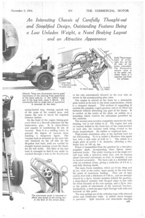
On the front of the engine timing-gear cover there is a Reavell exhauster for the brake-servo gear. It is chain-driven and capable of maintaining 24 ins, of vacuum. Near it is a sniffing valve, to prevent the degree of vacuum from reaching a dangerous figure. The vacuum tank is mounted on the near side and balanced on the off side by the 20-gallon fuel tank; both are carried by straight bearers running across the frame for the full width. The filler of the fuel tank is arranged so that it can easily be reached through a hole in the floorboards
of the cab, conveniently situated on the near side, as shown in the accompanying plan view.
The engine is carried at the front by a detachable plate bolted at its ends to the front cross-member, which is a dropped channel. This method Of supporting it enables the complete engine-gearbox unit to be lifted out forwards without disturbing any part of the frame. It is carried, at the centre of the plate, on rubber, in a mounting which restricts the movement permitted by this material.
The second cross-member completely encircles the bellhousing, but is not bolted to it. The engine feet rest on bearers bolted to the front face of the cross-member at each side, the 'member itself being riveted to the frame longitudinals. No rubber is employed here.
High-tensile aluminium alloy is the material used for the bell-housing. To it is bolted a Meadows four-speed box with a first ratio of 6.83 to 1. The clutch is a. single plate of nearly 1 ft. diameter, affording a frictional area of 133 sq. ins.
Power is transmitted from the gearbox by a two-piece propeller shaft, incorporating three Spicer metal, universal joints. The centre bearing is of the single-row ball type with a spherical outer race, and its housing allows universal movement, so that, in assembly, it can be located accurately. The back axle is a Kirkstall unit with an overhead worm, giving a reduction of 6.5 to 1, and fully floating shafts.
The main frame members, which are 8 ins, deep and 21 ins, wide at the centre, taper gently to the rear from the point of maximum loading. They are of high carbon steel with a thickness of 7-32 in., and are strongly braced by a 31-in. tubular member behind the gearbox, a deep-shaped member with flanged edges in line with the front brackets of the rear springs, and a 21-in. tube at the points of attachment of the rearmost brackets. Incidentally, a steel bar goes right through both tube and brackets at this point.
The rear springs are of the orthodox type with rebound plates and substantial bolts. A rubber shock bumper is provided. Split brackets and detachable shackles 833 enable the complete axle and spring assembly to be removed from the chassis as a unit.
A new T-type Dewandre vacuum cylinder assists the application of the foot brake. It is mounted at the front to the rear engine cross-member, and at the back. to a bracket bolted to the frame, which balances the tendency for the rear of the cylinder to move upwards in operation. The vacuum valve is incorporated in the pedal rod, whilst a separate rod connects the cylinder-operating lever with the brake cross-shaft. There is a third rod from the hand lever to the cross-shaft. An adjuster is incorporated in each of these three rods.
The cross-shaft has two spherical plain bearings at its ends and a spherical ball bearing between the hand and servo arms. To resist torsion, the longer portion of the shaft is of enlarged diameter. The three arms to which the operating rods are attached are of the knuckle-jointed type incorporating lost-motion devices, whilst at the ends of the cross-shaft double-ended arms transmit the pull to the front and rear brakes. In the former case, straight rods run to the brake camshafts, whilst, in the latter, two-piece rods, supported at the joints, are used.
The points of attachment of the front brake rod are so arranged as to be in line with the top leaf of the front spring on each side in order to minimize the influence of motion of the axle relative to the frame, whilst, with the same object, " hook-up " levers are provided in the rear brake lines at the points where the rods pass the spring brackets. The longer rods run through guides to check vibration.
Although the steering box and drop arm are at the extreme front of the frame, the front springs are pinned at the rear and shackled at their forward ends. As in the case of the brake gear, however, the steering joints are placed in line with the rear point of attachment of the offside spring.
To bring the brake lever within easy reach of the driver.
it is bent well forward, whilst, with the same object, the gear lever is similarly set and the gearbox mounted at a slight angle to lean the lever to the off side. This enables full advantage to be taken of the central ball-type change, and obviates the need for linkage. The manner in which the front wings are mounted is worthy of note, in view of the rigidity afforded. The imposition of a man's weight on the front of one of them causes no appreciable deflection of the structure. They are supported at the back by outside angle-section brackets bolted to the frame; these also form supports for the cab floor.
Under each wing at its highest point there is a stiffening piece, the support here being the scuttle forming the front of the cab. At the lower extremities of the swaged lines there is a third attachment to the dumbirons. The scuttle, incidentally, is designed to fit over the woodwork B34
of the body, thus MA ktng a watertight joint, and to permit easy removal of the radiator.
The following are miscellaneous details that deserve mention :—To provide the additional power required for starting the oil engine an accumulator of 130 ampere-hours' capacity is used; it is neatly accommodated on the cab floor where it will be below the driver's seat. The bonnet is secured when closed by neat Amal clips. A detachable plate behind the bonnet gives ready access to the clutch pit. The back end of the bonnet slopes in such a way as to promote the flow of air past the engine and away under the chassis. A large Tecalemit filter is mounted im mediately below the Autovae behind the scuttle on the near side of the bonnet.
The instrument panel is carried so that the back of the switch can be easily reached and access gained to the backs of the gauges and speedometer through a detachable cover on the scuttle.
The chassis is comprehensively equipped and a stop light is inchided in the standard specification. In this connection, it is of interest to note that no equipment of any sort is attached to the body : the chassis is entirely selfcontained. Standard tyre equipment consists of 34-in. by 7-in. Goodyear high-pressure pneumatics, with twins on the rear wheels.
This model, which is designated the PF. 130, is available with two wheelbase lengths-13 ft. and 12 ft—the maximum body spaces afforded being 15 ft 10 ins. and 14 ft. 5i ins, respectively, whilst the height to the top of the frame, when laden, is 2 ft. ins. The price, in both cases, is £695, at which figure we surmise that it will be accorded the good reception it deserves.
Our readers will remember that some months ago we carried out a road test of the Gilford Hera chassis, introduced about a year ago. Among other comments we then made about this machine, were references to the high quality of workmanship and attention to details that were revealed by an examination of the design. Although we have referred, on a preceding page, to the simplicity of the new model, there has been no lowering of previous high standards; furthermore, the power unit is of a now wellestablished design which has earned for itself a fine reputation. It is typical, however, of the thoroughness of the Gifford company that it should make its own modifications before accepting the engine for use in its new chassis.
the top water connection.