


New Principle in
Page 44
Page 45
Page 46
If you've noticed an error in this article please click here to report it so we can fix it.
THE LATEST ARMSTRC
\G-SAURER OIL ENGINES
by Screened Inlet Valves
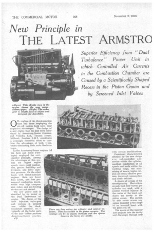
0 IL engines of the direct-injection type and those employing the air-cell system both have their respective advantages. The design of a new engine that has just been introduced by Armstrong-Satuer Commercial Vehicles, Ltd., Thames House, Millbank, London, S.W.1, constitutes a seemingly successful effort to combine the advantages of both types, whilst eliminating their main disadvantages.
Earlier Armstrong-Sanrer engines (of the Acro and Cross Flow types) employed the antichamber principle. Among the advantages of this system are higher engine speeds, more rapid combustion, greater flexibility and liveliness, and lower injection pressures. On the other hand, with direct-injection engines, there are lower heat losses, and less pronounced combustion knock, whilst very high compression ratios and pre-beating devices are not needed.
The new power unit is described by its maker as the Dual Turbulence oil engine. The design of the head injectors, valve-gear and pistons is entirely new, whilst the block, crankshaft assembly, etc.— virtually all the lower parts O1 the unit—follow previous Armstrong-Saurer practice, B2S; with certain modifications.
Prominent characteristics afforded by the new design a r e well-controlled a i rmotion within the cylinder, excellent combustion at all speeds and loads within the working range, the minimizing of knock, higher output and mean effective pressure, improved consumption and clean exhaust.
A glance at certain of the accompanying illustrations reveals that four valves per cylinder are used, with a central vertical injector in the centre of the head, and shows the cavity in the piston crown. The section of this recess across any piston diameter is the shape of an inverted heart with the point cut off.
The nozzle of the injector just projects into the-cavity and discharges through four
equi-distant radial orifices, which are approximately in the plane of the top of the pistOn, when. in its uppermost position. Both inlet valves arc shrouded for a portion of their circumferences, the shrouds, or screens, being so placed as to impart a tangential motion to the incoming air.
This description of the parts responsible for the air turbulence and for the manner in which the fuel is injected v,ill enable the following outline of I‘liat goes on in the cylinder to be followed. The phrase "‘ Dual Turbulence" has been chosen as the name of the design, because the air is given two distinct simple motions which combine and form a complex rotation about two axes. . .
During the induction stroke, the tangential motion imparted' by the screened valves causes the air to rotate at extremely high speed about the axis of the cylinder. This motion is maintained and is still extremely rapid at the commencement of combustion. While the piston is rising, the stream of air entering the piston cavity impinges on the pointed projection at the bottom and " is given.: a rotational motion about an axis which may be imagined as a ring formed by the centres of the vertical circles bounding the cavity.
These are. the two simple 'Motions: Their effect is a high-speed air stream following a corkscrew -path in the cavity around the centre line of the cylinder, and travelling at the -.top (so far as the vertical motion is concerned) towards the injector .nozzle. ,
So boon as the four jets of fuel are discharged intothis stream, the globules are at once picked up and distributed throughout the chamber, being subjected in the process to a violent scrubbing action and rapid heating.
It should be noted that the air travels at a speed proportional to that of the engine. A figure quoted for the horizontal rotational speed is 7,000 r.p.m.
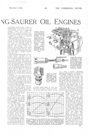
It has been found that the angle at which the shrouds on the inlet valves are set is of great importance. Accordingly, provision has been made for accurate adjustment. Each valve at its upper end has a flat, formed on the stem; the lower spring-cup is slotted and correspondingly shaped.
Between the cup and the top of the valve guide is a _knurled distance piece, haybig on each face a ring of dowel-pin holes—eight on one and seven on the other. There is a dowel pin on the guide and another on the cup. Thus a vernier adjustment, affording 56 positions, is provided for the angular setting of the shroud.
The correct settings are such that the angle between the cylinder diameter, through the valve centre, and the radius from the mid-point of the shroud, in the case of the first valve (considered in the direction of air stream), is 15-20 degrees, and, in the case of the second valve, 80-90 degrees.
The new injector is of interesting construction. An accompanying sketch' shows its parts and their arrangement. Each injector is inserted. through a housing permanently screwed into the head through . the water jacket. This practice, incidentally, greatly simplifies the casting. It will be observed that the bottom of the body, which is exposed to the heat of combustion, is slotted, the object being to avoid alterations in its bore through temperature variations. Within it is the nozzle, and, inside that, again, the needle. The smaller diameter of the lastnamed has clearance in the nozzle for the passage of fuel, but is a sliding fit, at its larger diameter, in the guide, which is made as a separate part and placed well away from the hot end.
The needle has two differential: faces and is screwed internally at the upper end for easy extraction. The diameter of the four nozzle orifices is 0.25 mm. (about 0.01 in.).
Besides affording higher volumetric efficiency, the use of four valves per cylinder enables the injector to be placed centrally. The practice has other advantages, but complicates the problem of designing an operating gear. The difficulty has been satisfactorily overcome, however, by the ArmstrongSa.urer designers. The two inlets and • exhausts are placed in transverse lines across the head. Two rocker shafts run lengthwise outside the valves ; they are carried in aluminium-alloy bridgepieces. Push-rods on one side operate the nearest row of valves, through rockers in the usual way, whilst extensions on the ends of the rockers bear on further rockers, which actuate the row of valves remote from the pushrods.
There is an adjuster for each pushrod, and another for each valve depressed by the main rockers. No adjusters are provided in the secondary rockers. There is a roller in the ex
tended end of each main rocker wnere it bears upon its confrere. All bearing surfaces are hardened steel and lubricated by oil, fed from the hollow shafts. The whole rocker-gear assembly can be lifted off as a unit.
With regard to the general improvements mentioned earlier, one specially noteworthy alteration is found in the cooling system. Water is now delivered from the pump, to the back of the block, and to the head on the near side, at points adjacent to every group of valve seatings. Thence it returns from the off side of the head to the radiator.
As in the past, a built-up roller' hearing crankshaft is used. A springloaded balancing cam, to give constant load, is incorporated in the camshaft.
The C.A.V.-Bosch or Scintilla injection pumps are employed. The pistons are Specialloid products, and the Hsection connecting rorls, machined all over, have white-metal-lined two-bolt big-ends.
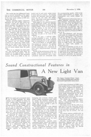
Details of the performance of the new design, which is incorporated in two models—a six-eylindered and a fourcylindered unit—are obtainable from the accompanying graphs, which show marked improvements in output and consumption over earlier designs of engines.
We understand, furthermore, that excellent indicator diagrams have also been obtained. Outstanding characteristics are said to be the almost complete absence of delay period at the commencement of injection, and the low peak with rounded top. The engine has a compression ratio of 15 to 1. whilst the injection pressure is 3,000 lb. per sq. in.
The four-eylindered and six-cylindered units are designated types BOD and BLD respectively ; with cylinders of 110 mm. by 150 mm., their capacities are 5.7 litres and 8.55 litres. Outputs of 70 b.h.p. and 120 b.h.p. are given at 1,800 r.p.m., the crankshaft speed at which both models are governed to run.
Our close examination of one of the new engines, and our brief experiences of a unit on demonstration, enable us to appreciate the company's confidence in the future of the new design and in its complete suitability for passengervehicles, as well as for goods chassis.