


NEW HYDRAULIC TRANSMISSION.
Page 58
If you've noticed an error in this article please click here to report it so we can fix it.
A Résumé of Recently Published Patents.
We have dealt from time to time in these columns with that form of transmission in which a practically incompressible fluid, such as oil or water, serves as the medium through which the engine power is transmitted to the rear axle. The idea of an hydraulic transmission is extremely fascinating, and has for long been the subject of experiments and of invention, as it affords not only a noiseless method of transferring torque, but can also be made to give an infinite variety of gear ratios ranging from a direct top gear to a free engine. Many of those forms of hydraulic transmission, which we have described here,. have embodied an engine-driven pump, which forces the liquid into the cylinders of an hydraulic motor. By varying the amount of slip which is permitted in one or other of these components the gear ratio is altered accordingly.
It will be evident that, if 100 per cent. slip is arranged, or, in other words, if the. engine-driven pump merely churns up the fluid, then there will be no transmission of power whatever, and this will correspond to the free-engine or neutral position of the ordinary gearbox. On the other hand, if the passages between a pump and motor are so controlled that no slip is possible and pump and motor will rotate en bloc as one unit, then the transmission will be a direct one. It can readily be nriderstood that this degree of slip can be controlled simply by means of a valve, and will afford every possible gradation between the two extremes which we have enumerated. There is no need for a cletch in the transmission.
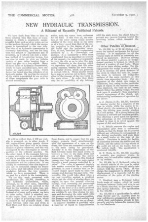
We are this week concerned with specification No. 151,308, describing a new hydraulic transmission, which, although, as in other cases, depending 'upon the amount of slip allowed to the fluid for the variation in ratio, beer, notwithstanding, several points of novelty. Instead of a pump and a motor, we have an outer casing, which is attached, say, to the engine shaft, and an inner drum with a couple of projecting vanes, which is coupled to the propeller shaft. The space between outer case and drum is fluid filled, and there are rotating drums B18
whiah, with the vanes, form enclosures for the fluid. If this were all, the rotation of the outer casing would involve rotation 'of the inner drum at the same or ataa lower speed than that of the easing, according to the degree of ,slip of the liadid past the 'projecting vanes. This, in fact,'Cledcribes the transmission invented • by L. K. aCheswright and another. It is necessarily a little more complicated ,is as described on account of the necessity for making arrangements to vary the slip £0 as to alter the gear ratio. Reference to the drawing which we reproduce will show that the outer casing coutaieselbesidea the main drum, Vero smaller drums, which are generally in contact with it. These smaller drums have gaps or grooves cut in them, which allow of the passage of the two vanes on the main drum. In order that there may be no possibility of slip between
these drums, and to ensure that the gap always presents. itself simultaneously with the appearance of a vane on the drum; the three are connected externally to the main, casing by gearwheels. Actually it is the compression of the fluid between these two small drums or between a vane on the main drum and one of them which effects the power transmission. The liquid in this blocked passage may leak out of the main casing through a small passage controlled by a valve. The valVe is operated through link motion controlled by a, centrifugal governer, in such a manner that an increased engine speed tends to close the passage and decrease the gear ratio. Presumably, this would tales effect when a car was travelling against a gradient which had the effect of slowing down the engine, to open the passage allowing leakage, thus increasing the percentage of slip and increasing] the gear ratio. When on the level or at a down gradient the engine speed is increased, the governor weights fly out; thus closing the passage and decreasing the ratio until, with the governor weights in extreme posation, the passage would be closed entirely and the ratio would be one to one or direct.
A separate chamber is provided with a reservoir of liquid in communication with the main drum, the object being to prevent any vacuum forming behind the revolving rollers which transmit the drive.
Other Patents of interest.
No. 151,350, by A.11.` G. Girling, concerns the control mechanism for friction clutches. It is applicable to all the various types of clutch as commonly employed in motorcars. Between driving and driven member a groove or wedgeshaped aperture is formed, in which are disposed a mother of steel belle. These rest on an inner sliding wedge. For disengagement the wedge is moved axially, so as to increase the pitch diameter of the circle in which the balls lie, thrusting them in between the wedge-like surfaces of the main members of the .clutch, thus separating them. For engagement of the clutch this wedge is withdrawn, but, owing to the particular angle of repose of the varioua taper curfaces employed, the balls do not immediately follow the sliding wedge, but fall back upon it gradually, thus ensuring a smooth engagement of the clutch, notwithstanding carelessness of operation by the driver.
A. J. Adams, in No. 151,357, describes an impulse starter for a magneto of the type in which, while the engine is revolved slowly, the armature is held for a time, the driving gear merely winding up a coil spring. At a given instant the armature is released and revolves quickly, thus effecting a good spark for ignition. The advantage of the construction described is that it is proof a.gainet the ingress of dirt and moisture.
J. G. Schulz removes the engine and transmission gear from a commercial vehicle, so that its design can be evolved without any reference to arrangement of the driving inechanistn, and puts them on a small trailer at the rear of the vehicle. Provision is made for facility of connection between the trailer and the vehicle, and the actual driving wheels of ,he outfit are not on the trailer, but on Te vehicle itself. The specification is numbered 151,376.
G. F. Wells, in No. 151,439, describes a portable gas producer which, he states, may be used either under pressure or by suction..
No. 151,454, by J. Bethenod, refers to an electric starter of the type in which the driving pinion is brought axially into contact with the driven wheel. In this design the engagement is effected by the displacement of a magnetic rod by the attraction of the poke of the starting motor. • T. Bradford uses a D-shaped hollow block made. of rubber, which he would interpose between frame and axle to act 'as aeshock absorber, in the ease of excessive spring deflection. The specification is Nos 151;466.
No. 151,425 is a specification in which John Fowler and Co. describe their by now well-known arrangement of gear, by which their anti-balance plough 18 temporarily put into balance for manceuvring at the headlands.