


A NEW BRITISH 25 CWT. CHASSIS.
Page 47
Page 48
Page 49
If you've noticed an error in this article please click here to report it so we can fix it.
A Detailed Description of the 25 cwt. Albion Chassis, Designed for the,Conveyance of Goods or Passengers.
-I VIEW OF the demand which has existed for some time, not only in this country, but also overseas, for a light but substantially built commercial vehicle designed to carry loads in the neighbourhood of 25 cwt., it is ;somewhat surprising to find that this demand is so badly catered for by British manu
facturers. Except in a few instances, they can offer 'bobbing between a light box van for loads of from 12 cwt. to 15 cwt. and thc two ton lorry; for anything between these prospective customers usually have to turn to vehicles' cf foreign manufacture' a position which is certainly far from satisfactory. A few manufacturers have, however, realized the necessity for producing chassis to carry loads of from 25 cwt. to 30 cwt., and amongst these the Albion Motor Car CAo., Ltd., of Sootstoim, Glasgow, are the originatcrs of a chassis which ES certainly a very commendable answer to the critics-who say that rear manufacturers cannot turn out a light chassis which -will compete against the foreign invasion.
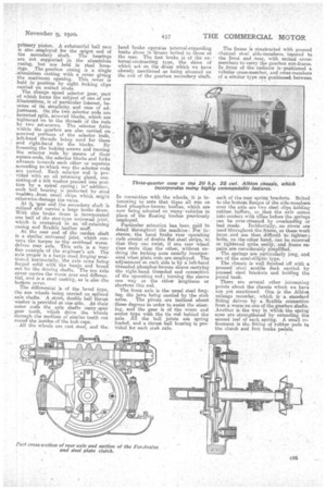
In 1914 the company were making a 15 cwt. worm-driven Chassis, but this was dropped during the war, and has now been replaced by the 20 hp. 25 cwt. machine. As a goods-carrying vehicle,
this chassis-'0 can carry body which_ roust not exceed 10 owt., but when employed as a 15-seater char-banes, the body weight can be 15 cwt. It can be
provided with pneumatic lyres on steel detachable wheels all round or at the front only; its normal speed with solid tyres is 18 m.p.h., or with pneumatics at the front, 20 m.p.h. The engine is governed to the necessary number of r.p.m. by a totally enclosed centrifugal governor operating direct on a separate
butterfly throttle situated at the top of the induction pipe.
The chassis has been designed with a view to fulfilling satisfactorily the most arduous conditions of employment both in this country and overseas It has a ground; clearance of 9i ins.' which enables the vehicle to travel over very bad roads without fear of damaging any of the units owing to direct contact with the road, wi sometimes happens when the ground clearance is small. Also, to ensure easy handling in confined spaces, the turning circle has been kept small, being only 42 ft. in diameter. Although the vehicle has been designed with a view to withstanding severe service, and for its rated capacity presents a very robust appearance, its weight has been kept comparatively low, the approximate weight of the chassis being 30 cwt. Another point is the low loading line, the distance from the ground to the trp of frame when the vehicle is laden being 2 ft. 4 ins.
Provision is made on the chassis for the fitting of a dynamo, and that recommended is the " Klersite," which is driven from a V-pulley integral with the fan pulley, and is supported on bracket bolted to the front engine bearer. On the armature shalt isa. governor pulley designed to keep the speed of the armature constant once it has reached the maximum fixed.
To proceed with a more detailed description of thechassis, the engine is a four-cylindered monobloc with all the valves on the near side and protected by a cast aluminium 1ate. The crankshaft is supported in the top half of the crankcase by three bearings and the cylinder head block is detachable, giving easy access to the pistons. The cast aluminium crankcase has the studs for Ow sump fitted into the -top half, so that. the nuts can be reached from below, when it is necessary to drop the eninp. A flexible leather coupling is employed in the magneto drive, the magneto being situated at the near side. The ignition wires are supported in red fibre blocks carried on abracket bolted to the exhaust manifold.
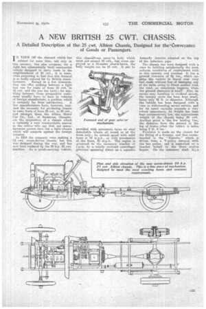
The system of lu.bricatien is of par.
ticular interest. -The lubricator is a Murray patent which supplies oil to 12 feeds, three of these leading to the main. bearings, four to the big-ends, a further feur to the -cylinders, and the remaining one to the governm gear situated in front of the engine. In this lubricator a -rotating member carries -a single plunger, which is given a vertical motion by means of fixed face cams; holes in a atationary plate, on which the rotating memilwer moves, correspond with the various oil leads, and the plunger delivers oil to each of these in turn. 'use amount of oil delivered can be varied from the exterior, the cams being arranged to give three different feeds, and there is also a hand flush to provide. extra oil for hill-climbing, so that there can be no excuse for either under Or over oiling. Carburation is attended to by an instrument of Zenith manufacture, and this has a hot air pipe leading from a. hoed situated above the ex{most manifold. A centrifugal pump, driven from an extension of the fan spindle, circulates the cooling water through the Jackets and through the castaluminium header-andbottom-tank t yp e radiator.
C24
The whole engine unit is mounted at three points on two pressed steel engine bearers. To prevent damage from vibration, the radiator is mounted between cushions at each side, one boltonly being employed. The cushiens are contained in neat pressed steel cases, which not only protect them, but also add to their appearance.
Following the most modern practice, a single plate clutch is employed. This is. -gripped between two rings of Ferobestos, -which is a pure asbestos friction
material without wire. One of these
rings is riveted direct to the flywheel, whilst the other is -carried by a pressure plate, the latter being pressed into engagement by square section coil springs. The pressure plate is withdrawn for disengagement through the medium of a collar carried on a radial ball bearing, and provided with aStout ball thrust. bearing. At the front end the clutch[shaft is cut with-spur teeth, and engages with internal teeth cut in theclutch centre, thus forming a type of universal joint with good wearing qualities and little liability to develop slackness. At the rear -end of the clutch-shaft is oarried a cone-shaped pressed steel clutch 'h-rake. . At the front end of the gear113ox primary shaft is another universal joint of the spur gear type, and great care is taken to prevent the loss of oil from thin joint. The male portion carrying the teeth is spherically shaped, as is the pressed steel cover bolted to the female portion-, and between the two is a leather joint. To keep this joint always under compression, a apical spring is inserted between the end of the clutch-ehaft and the end of the-primary shaft. Incidentally, this care to prevent leakage of oil has been Observed throughout the chassis.
A very substantial sub-frame is provided for the three-speed-and-reverse gearbox, which is supported at four points. The sub-frarne is suspended from two channel section cross-members, and at its front end carries the clutch pedal shaft. The change speed and brake levers are carried by a bracket 'bolted to the frame side-member on the off side. Although this construction sometimes causes binding of the change-speed lever, in the 25 cwt. Albion chassis this fault is entirely absent, as the gearbox sub-frame 'and cross-members form a rigid square -unaffected by frame twist.
Ball bearings are employed throughout the gearbox and a double ball thrust race is incorporated at the end of the secondary shaft. Two splined sliding pinions are ernployed, and the drive is direct on tep, internal teeth on the top and second speed pinion meshing with the teeth on the primary pinion. A substantial bail race is also .employed for the spigot end of the secondary shaft. The bearin.gs are not supported in the aluminium casing, but are held in steel housings. The gearbox casing is a single „aluminium casting with a cover giving the maximum opening. This cover is held in position by eight locking clips carried on nutted studs.
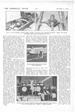
The change speed selector gear, part of which forms the subject of one of our illustrations, is of particular interest, because of its simplicity. and ease of adjustment. On the two selector rods are mounted split, screwed blocks,..which are tightened on te the threads of the rods by two set-screws. The selector forks within the gearbox are also carried on screwed portions of the selector rods, left-hand threads being used for these and right-hand for the blocks. By loosening the locking screws and turning the selector rods by means of their square ends, the selector blocks and forks advance towards each other or separate according to .which way the selector rods are turned. Each selector rod is provided with an oil retaining gland, consisting,of a felt washer pressed into position by a spiral spring; in' addition, each ball bearing is protected by steel washers .from small chips which.. might otherwise.dam,age tire races. At it 'rear end the secendary shaft is Splined• end carries' a large brake drum. With this brake drum is incorporated one half of the star-type universal joint, which is contained in an oil-retaining casing and flexible leather muff.
At the rear end of the carcla,n shaft is a similar universal joint, which conveys the torque to the overhead worm driven wear axle. This axle is a very fine example of the engineer's art. The axle proper is a banjo steel forging positioned horizontally, the axle arms being forged solid with the banjo and bored out for the driving shafts. The top axle cover carries the worm gear and differential, and is a teel casting, as is also the bottom cover.
The differential is of the bevel type, the sun wheels •being carried on. splined axle shafts. A stout, double ball thrust washer is provided at one side. At their outer ends the . axle shafts carry spur gear teeth, which drive the wheels through the medium of similar teeth cut round the insides of the hub cape. All the wInels are cast steel, and the hand brake operates internal-expanding brake shoes in 'drums bolted to those at the rear. The foot brake is of the ex' ternal-contracting type, the shoes of which act on the drum which we have already mentioned as being situated on the end of the gearbox secondary shaft.
In connection with the wheel, it is interesting to note that these all run on fixed phosphor-bronze bushes, which are now being adopted on many vehicles in place of the floating bushes previously employed.
Particular attention has been paid to detail throughout the machine : For instance, the hand brake rear operating rods consist of double flat steel strips, so that they can twist, if one rear wheel rises more than the other, without undoing the locking nuts usually incorporated when. plain rods are employed. The adjustment at each side is by a left-hand threaded phosphor-bronze sleeve carrying the right-hand threaded end connection of the operating rod • turning the sleeve one way or the rod; lengthens or shortens this rod.
The front, axle is the usual steel forging, the jaws being carried by the stub axles. The pivots are inclined about three degrees in order to assist the steering, and the gear is of the warm and sector type with the tie rod • behind the axle. All the ball joints are spring loaded, and a thrust ball bearing is provided for each stub axle. The frame is constructed with pressed channel steel side-members, tapered to the front and rear, with arched crossmembers to carry the gearbox sue-frame. In front of the radiator is positioned a tubular cross-member, and cross-members of a similar type are positioned. between
each of the rear spring brackets. Bolted to the 'bottom fianees of the side-members over the axle are two steel clips holding rubber beffers, so that the axle comes into contact with thOse before the springs can be over-stressed by overloading or bad roads. Incidentally,no rivets are used throughout the frame, as these work loose and are then difficult to. tighten ; bolts, on the other hand, can be renewed Or tightened quite easily, and frame repairs are considerably simplified.
The springs are particularly long, and are of the semi-elliptic type.
The chassis is well finished off with a pressed steel scuttle dash carried by pressed steel brackets and holding the petrol tank.
There are several other interesting points about the chassis which we have not yet mentioned. One is the Albion mileage recorder, which is a standard fitting driven by a fietible connection from a worm on one of the geaaobox shafts. Another is the way in which the spring eyes are strengthened by extending the second leaf of each spring. A small refinement is the fitting of rubber pads to the clutch and foot brake pedals.