


A NEW CHANGE-SPEED GEAR.
Page 30
If you've noticed an error in this article please click here to report it so we can fix it.
A Resumeof Recently Published Patents.
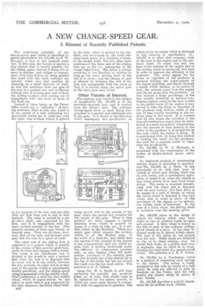
The underlying principle of the change-speed gear which is described in patent specification No. 151,144, by F. W. Sturgess, is that of the constant mesh box. In this case, the feature is carried a step further than is usually possible, for the sliding gears, instead of being two or more in number, and subject to engage.. moot with their fellows by being pressed into mesh with the teeth endways on, actually climb into that position by wheeling up a spiral staircase of teeth, so that the transition from one gear to the next is a gradual one, and is effected without risk of missing gear and without the sliding member over coming out of engagement with the teeth of those of the fixed one.
Instead of there being, as the Patent Office would say, a " plurality " of moving members, there is only one, which is in the nature of a fork embracing two gearwheels which are in meslieone with the other. One cif these wheels is splined to the layshaft of the box, and can slide with the fork from end to end of that layshaft. The other is carried by a pin or shot shaft, also supported by the fork, and is in engagement with the main toothed member of the box. This actually consists of' three spur wheels, of varying sizes. They are alkthree, however, part of one unit, and between each gear and the next is a spiral of teeth.
The outer end of the sliding fork is supported M a groove' Whial is parallel . to the surface of this peculiar gearwheel, while its hmer end engages with a worm. The worm is not contihuous, but is divided in the centee in such a manner that when the foil, is so disposed' that its jnner end is in the middle between the two portions, its outer -end is in that part of thiegroovei which is oppositeathe middle.gearwheel, and the change-speed whfal iejnncabed wit,h.te middle wheel. The transmission is then via, that middle *heel, which it engine-driven. 'to thewnpei in mesh with-it and supported by the fork, thealea to the Mlles 'wheel 'With
B32"
in the fork, which 'is splined to the layshaft, and afterwards by the usual constant mesh gears; or a variation of them, to the cardan shaft. The two other main positions elf the inner 6nd of the sliding fork are at the twe extremities of the worm-respectively. The latter is always revolving in one direction or another so long eis the main driving shaft of the box is in motio.i and the change of gem:, is effected by bringing the end of the fork into engagement with the worm so that it is moved along the spiral gear to the next. plain spur wheel.
Other Patents of Interest.
The starting gear which is the subject of specification No. 151,099 is of the manually-operated type, and is worked from the driver's seat. The ordinary change-speed lever is used, 'being reciprocated in a special and additional slot in the gate. It is shown in the drawings which acoompaay the specification as
being moved over to the outside of the gate, where the special slot occupies the full length of the gate. When in that position the lover engagesa special selecting lever, which is coupled by means of a train of rods, etc., to a ratchet clutch on the flywheel. There is a safety sear which releases the ratchet,. which is of the friction type, in the event of a hack-fire, but Which does not operate if the reversal of the engine
lithe comparatively slow one which re, sults from it turning backwards under
the. influence of -compression pressure only, as may Nippon when the preliminary novement of rho starting gear has just brought one of the pistons up to the top of the stroke but has not moved the crank over the top dead centre. The patentee is A, J. Adams.
Lieut.-Col. fl: 5. .Smith is still busy perfecting his portable .gas producer plant, or, at least, that would seem to be indicated bythe patent reeords, in which his name again figures in connection with 016 apparatus in question. The object of the invention which is disclosed in this instance in specification No. 151,087 is to effect dual economy, both of the heat in. the engine and in the producer itself. To attain this end, the heat of the exhaust of the engine and of the cooling water is conserved, and used in order to improve the efficiency of the producer. The water siepply for the boiler or vaporizer, of the producer is pumpedthtough the water-jackets of the engine cylinders, and thence through a heater which utilizes, as its source of heat, the exhaust gases from the engine and the hot gases from the producer. in this manner a large percentage of the loss usually occurring in internal-combustion engines owing to the heat wasted in the jacket water of the engine is conserved to heat the boiler or vaporizer of the producer and, further„ much of the loss of heat usually occurring in the exhaast gases is also saved. It is claimed that by this means the cylinders of the internal-combustion engine may be maintained at, a more economical temperature, and the amount of heat passing to the water of the producer is in proportion to the-work which the engine is doing. It is anticipated that, by using this method of heating the water for the producer, the need for a separate boiler or vape
riser can be obviated. .
No. 151,060, by W. S. Hickman, is concerned with the construction of the bodies of double-decked. motor (Minibuses.
An improved method of constructing electric chassis is described in specification4NO. 151,035, by J. Scott. It has principally to do with that type of vehicle in which each driving wheel has its own motor, and is partinularly applicable, it seems to us, when the vehicle is four-wheel driven or at least front-wheel driven. The motor is mounted immediately over the wheel and is disposed with its axis vertical. The final drive is by means of a pair of bevels, of which the crown wheel is fastened to the road wheel, and, in order to allow of the movement of the chassis on its springs, • the cardan shaft is.:ktelescopie. In the ease of' a front wheel, the driving shaft is vertically over the steering pivot.
No. 136,832 refers to the design of wheels for vehicles which may have either to run on common roads or upon soft ground. A false wheel is:bolted to the side of each of the ordinary rubbertyred wheels Of a lorry. It has deep'Vshaped spnds on it, spaced widely apart. The tens of the spuds do not project over the tyre. "Other spuds are designed to clip on to these existing, ones, for actual field work, or a spring steel rim, in segments, may be fitted on to them, farming the equivalent of a smooth-tyred wheel. The patentee is C. E. P. Julien.
No. 130,606, by A. Deschamps, refers to a method of connecting road springs to the chassis. The snring -is freely mounted on _the axle by means of a ball joint 1. its ends are allowed to slide in brackets . on the frame, and the axle pushes the' chassis along by' Means Of
horn blocks. • N. 151,223 describes a pedrail attachment for an endless track vehicle,