


Modern Suspension Systems in Theory and Practice
Page 22
Page 23
If you've noticed an error in this article please click here to report it so we can fix it.
In this, the first of two articles on the subject, the author, amongst other matters, deals with periodicity, the gyroscopic effects of front wheels, the resistance to rolling and the importance of correct front-wheel angle
I T is only in recent years that the full importance of the . suspension system of the motor vehicle has become fully realized, and although present conditions do not warrant the intensive research which has been given in this direction to private cars, there is always the possibility of the birth of a new 'tolerance on the part of the powers • that be to the potentialities of the road motor.
The high-speed coach of the future will most certainly require to have the full benefit of the knowledge. of the suspension engineer if it is to give the standard of comfort and safety which the conditions will demand.
From the discussion which centred around the. Burgess suspension some time ago in this journal, it would appear that some of the first principles are not yet understood, although the sometimes false •information • which is disseminated from publicity departments is not conducive to an accurate comprehension.
The Importance of Correct Springing .
Springs are fitted to a motor vehicle primarily to soften the effects of road impacts,. but the satisfactory solution of this requirement does not end the task of the suspension engineer, for the steering, general handling and minimization of tyre wear are all directly affected. To consider the problem of comfort first. An impact applied to the wheels of a motor vehicle such as results when meeting a bump on the road will cause the axle to rise, and if the springs be extremely hard the body will lift at almost the same velocity as the wheel, with the result that tl.e occupants would receive a violent shock. It is, therefore, essential to soften the springs so that the axle rises quicker than the body. If the wheel be held at the top of the bump, the spring, being deflected, 'Would unload by lifting up the body.
The softness of a spring, on commercial vehicles especially, is dictated by the clearance .which may be permitted between the axle and the frame, and on the frequency of the vibrations which follow the initial impact. For reasonable riding comfort the permissible number of vibrations per minute is between 110 and 70, this being termed the " periodicity." This is dependent on the deflection of the springs under the load of the vehicle when it is stationary, so that it follows that comfort is ' dependent on periodicity. The only modifying factor to this statement is the influence of the friction which occurs from leaf contact and shock absorber effect, although they do .not affect the theoretical figure to any great extent.
' It is important to realize that periodicity refers to the movement of the sprung mass and in no way is to be considered as the spring frequency, as it is so frecjleently termed. It is the wide use of this incorrect term which has led inVentors to fit dual springs to each
wheel in the belief that they have different and, therefore, counteracting frequencies. No matter how the springing be arranged, if the body be set in motion the number of vibrations per minute is dependent only on the deflection of the springs from the unloaded to the loaded position (Fig. 1).
On commercial vehicles the criticism of unduly hard springing, which frequently crops up, would not occur if this principle were fully understood, Accepting the statement already made, it will be obvious that, with a deflection giving a periodicity suitable for comfortable loading with an unladen vehicle, the addition of the payload would result in a deflection beyond 'reasonable bounds.
The best compromise which can be made in this direction is to employ overload leaves, which cause an increase in stiffness after a given deflection has been attained, although the incorporation of a well-sprung seat is undoubtedly the best answer.
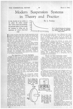
Wheels and Their Gyroscopic Action Next, consider .a revolving front wheel, which resembles a gyroscope in being capable of turning about the vertical axis of the king pin and a horizontal axis when one wheel is lifted after passing over a bump. In addition, there is its normal revolution on an axis which is simultaneously at right angles to both other axes. A gyroscope has a remarkable property in that, if the axis of the spinning wheel be displayed sideways, -assuming the mechanism to be spinning about a vertical axis, then it will tend to move sideways in a violent' manner at right angles to the applied force.
It must be understood -that a pure sideways motion of the mechanism as a whole will have no effect; it is when one end of the spindle is pushed over, leaving the other end in position, that this phenomenon occurs. In other words, the displacement must be of a rotary character (Fig. 2). The front wheels of a motor vehicle behave in a similar fashion to a gyroscope in that the lifting of one wheel by traversing a bump causes the tilting which instigates gyroscopic torque, and the wheel tends to rotate about an axis at right angles to the first two orbits of rotation, i.e„ the wheels tend to revolve about the king pin.
On beam-axled vehicles both wheels must obviously be tilted by the same amount so that a disturbing force will be instigated by each front wheel, and, although the friction of the steering mechanism must be overcome, in extreme circumstances it is possible for a dangerous condition to arise. The magnitude of the gyroscope torque is dependent directly on the mass of the wheel and the velocity with
which it is tilted. • .
On a given Vehicle, therefore, it is possible to reduce the force only by stiffening the springs or by reducing' the tilt of the wheels. Lack of balance in a wheel can have unpleasant results on the suspension System, as the tendency of a .heavy revolving mass is to move about its centre of gravity, If this be not coincident with the rotation centre then the latter will, itself, be revolved, proclaiming itself in a vibratory motion of the wheels in a fore and aft direction. Owing to the trail necessary to give a castor action, the movement of the wheels tends to shift the axle sideways :beneath:, the frame with a result similar to the• gyroscopic force,
Roll has important effects on the handling and safety of the vehicle and, therefore, the behaviour under this condition must be studied.
When a side load is applied, the sprung mass will rotate
about an axis along the centre line of the CllaSSIS. This roll axis connects two hypothetical points on each axle which represent the instantaneous centre of rotation of the 'mass dependent on the gecrmetry of the system employed. The rolling moment is dependent on the force applied, and the distance (" h," Fig 3) between it and the roll centre, so that, for a given centre of gravity, the higher the roll centre the smaller will be the rolling moment.
The resistance to roll depends on the stiffness of the. spring and the square of the spring spread (" b," Fig. 3). Orthodox beam-axled vehicles, therefore, although • fairly satisfactory in that the rear springs can be widely, spaced, are unfavourable on the front axle as clearance must be allowed for the Wheels to be locked over. Some mitigation of this accrues in the resistance of a: laminated spring to torsional deflection, and a high proportion of roll resistance results from this feature.
. The Problem of Side Sway Side sway is the side movement of a vehicle, as opposed to roll, when angular units are used. On double-decked buses the problem of side sway becomes of vital importance, for not only must the comfort of the passengers be considered, but the shift of the weight to one side makes for instability of the vehicle.
Tyre behaviour .under such conditions has been studied only in recent years, and owing to the research work done on this subject, safety and ease of control have been considerably improved. • Let us consider the forces applied to a tyre when a bend in the road is negotiated. First, .the weight on the outside wheels is increased and that on the inner ones correspondingly decreased, while, at the same time, the centrifugal force due to turning tends to push the tyre Sideways. Far from following a constant path the tyre, under these conditions, drifts in the direction of the force so that the tendency is to follow a path of increasing diameter (Fig. 4). The extent of this deviation under a given side load is dependent on the tyre pressure and the additional trans
ferred load.
On a vehicle with soft front suspension a more dispropor
tionate load would be transferred to the rear outside wheel, and the rear end would ,drift, more than the front, Consequently the tendency would be for the back end to swing out and the vehicle would assume an attitude towards its theoretical path of increasingly greater magnitude. This is known as oversteer, whilst the reverse, in which the front end drifts most, will give an understeer effect.
Springs and Steering Accuracy For ideal conditions a small amount of understeet is desirable, but this cannot be obtained with the orthodox chassis. Although. the front springs are somewhat stiffer than the rear the narrow spread reduces the transferred load to the front wheels so that the rear ones carry an excess share. The addition of an anti-roll bar enables this condition to be modified, but introduces new difficulties.
A further factor in this problem of steering accuracy is the arrangement of the springs. Some change in the angle of the axles with respect to the centre line of the vehicle occurs when the springs are deflected, and by careful design it is possible to balance the understeer effect of an axle skew by the oversteer effect of side drift, and vice versa.
The angle of the wheel is important, not only when
considered in plan, but also in end elevation. Normally, front wheels are arranged to run at a slight angle to the perpendicular, but with some of the newer suspension systeins the wheels may run at quite large angles to the 'perpendicular; In this case the radius from the centre of the Wheel to the contact tointa of the road will differ when 'measured at different points along the stub axle. If the wheel were made from a large number of thin discs made up to a width equal to the existing wheel, when travelling in a straight line, the lamination with the smallest radius 'would make MOM revolutions than the larger ones. The only \fray in which true rolling could result would be to allow the wheel to run in a circle so that the radius of the smallest disc was of the same ratio to the distance between it and the centre of turn as the largest disc and its centre of turn: Therefore, if a tyre be run at such an angle to the roaO as not to perniit a line, produced through the stub axle, to intersect the point of contact of the tyre with the road, slippage will occur and tyre wear result (Fig. 5).
From this same cause a tyre which runs at an incorre.ct angle to the road will tend to run at.the radius for correct rolling, the force thus caused being termed camber thrust. On beam-axled vehicles no trouble can arise from this cause as The extent of the camber employed is balanced out from the opposite inclination of the two wheels. On the other hand, certain independent suspension systems are characterised by similarly inclined wheels when turning so that the camber thrust is cumulative .and, therefore, steering accuracy is affected.