


Novel Design of Poppet Valve
Page 52
If you've noticed an error in this article please click here to report it so we can fix it.
A Résumc of Recently Published Patent Specifications
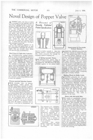
APOPPET valve, the stem of which is arranged on the opposite side of the head to usaal practice, is shown in patent No. 503,577, by W. Smith, 160, Stratford Road, Sparkbrook, Birmingham. The objects of this design are to provide a passage free from the usual obstruction caused by valve stem and guide, and to prevent the stem being scoured by the hot gases. Reference to the drawing will show that the head (4) is placed in the usual position, whilst the stem -(3) extends upwardly to receive the closing spring (1). A rocker lifts the valve, leaving a clear passage in port (5).
The chief objection appears to be that the stem and guide have to seal the compression, although the inventor claims that an oversize stem, fitted with grooves (2), is satisfactory.
Hard Liners in Light-alloy Cylinders.
ACENTRIFUGAL casting process, by which it is possible to cast-in a hard-metal liner into a cylinder made of a low-melting-point alloy, is shown in patent No. 503,992, by Fichtel and Sachs, A.G., Schweinfurt, Germany. The cylinder is first cast in the soft metal, such as aluminium, and is then placed upon the machine shown in the accompanying drawing. The molten hard metal is poured into the cup (1) while rotating at a high speed; the cup is also moved up and down. The hard metal issues from the spout, and welds itself to the cylinder wall without, however, conveying sufficient heat to melt the cylinder.
Pressure-operated Injection Control.
FROM Scintilla, Ltd., of Soleure, Switzerland, comes patent No. 503,653, disclosing a method of adjusting the timing of an injection pump by means of a pressure-responsive device operated by the fuel-raising pump.
The accompanying drawing shows the fuel-raising pump (left) and (right) the timing control on the end of the driveshaft of the injection unit. In operation, the gear-pump draws in fuel via port 6, and delivers it to the injectioii supply via port 7. At speed a restricting valve (8) causes a pressure rise in chamber 1 and this is transmitted, via duct 5, to hollow spindle 4. Here the pressure moves a spring-loaded piston (2), which advances the timing by turning a splined coupling (3).
A Spring-expanded Piston.
THE spring-backed piston ring is I now a well-established component, and patent No. 503,456 shows the same principle applied to the piston itself.
The patentee is C. Johnston, 1201, 32nd Street, Oakland, Cal., U.S.A. This inventor inserts a hairpin-shaped spring-steel expander in a slot in the piston skirt, so that the diameter of the skirt is maintained constant. The drawing shows a section cf the piston, with the expander (1) in position.
Obviously this device should compensate for wear of the skirt and enhance durability.
DATENT No. 503,713 comes from the
M.A.N. concern of Augsburg, Germany. The patent deals with a scheme for allowing instant discharge of the exhaust, a point of considerable importance in two-stroke engines. In this design the cylinder block is jacketed with large chambers (1) into which the exhaust can be immediately evatuated, via ports 3, with little back pressure. Further movement of the piston uncovers further ports which supply charging air from space 2. The usual water jacket is located adjacent to the cylinder, the exhaust jacket occupying space not normally utilized.
Hauling Winch for Bulky Loads.
DESIGNED primarily for the easy loading of tree trunks and similar bulky loads, a vehicle-driven hauling winch is covered by patent No. 503,720, by A. Mortensen, Hammel, Denmark. The accompanying drawing shows the arrangement, which is worked from a power-driven winding drum (2). The cable from this passes around guide pulleys to the cop of a removable upstanding arm (1), with means for height adjustment. The cable is attached to the load.
Piston with Soft-metal Skin.
rrHE results of considerable research 1 into piston and cylinder wear are disclosed in patent No. 503,949 (void), by E. Mahle, Bad Canstatt, Stuttgart, Germany. This inventor states that, with an ordinary light-alloy piston, the cylinder wears most at top and bottom with a less worn portion at mid-stroke. This means that the piston rings are flexed twice for every stroke.
H, however the piston be plated with a soft metal, such as tin, cadmium or lead, the cylinder wear is stated to he truly conical, with the larger diameter at the top. The piston rings, in this case, are flexed once only per stroke, and the resulting durability is said to be surprising. The beneficial results are attributed to the high degree of polish produced by the lapping effect of the soft covering.