


Three Noteworthy Lockheed Innovations
Page 47
Page 48
If you've noticed an error in this article please click here to report it so we can fix it.
An Improved Lockheed Gates Booster, a Two leading shoe Brake for Heavy Vehicles and Hydraulic Control for Doors and for Gear Changing, all Characterized by Marked
Mechanical Ingenuity
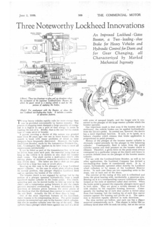
TO stop heavy vehicles rapidly calls for more energy than can be provided conveniently by human muscles. The process of stopping must dissipate a large quantity of energy and it is logical to use a part of that energy to assist in wasting the rest of it. Briefly, that is the case for the clutch type of brake servo or booster.
A patent covering a device of this, nature was granted more than 50 years ago—for use in horse trams!—but the system is beset with many problems of detail as later designers have frequently discovered. However, the Lockheed-Gates Booster, made by the Automotive Products Co., Ltd., 1.eamington Spa, appears in its later form to meet all requirements satisfactorily. • It can be fitted as part of the transmission line, or it can be driven from some such part, the essential being that so long as the vehicle is in motion so also shall the booster shaft rotate. This shaft carries a multi-plate clutch with driving plates of frictional materials sanclwichol between iron driven discs. The latter are free to slide on two pins attached to a large face cam or swash plate.
Bearing on this cam is the plunger of a large Lockheed master cylinder. As the cam or swash plate revolves from its normal position, this plunger displaces Lockheed fluid and so operatic the brakes of the vehicle.
The booster clutch is not engaged by springs but by the motion of a plunger operated hydraulically from a small Lockheed master cylinder at the brake pedal. The clutchactuating unit can be moved, bodily to take up wear in the clutch and a compression spring between it and the clutch prevents excessive overloading. A detail refinement is the provision of distance pieces between the metal plates of the clutch so that the frictional discs cannot be worn beyond the safe limit. Actually the life of these discs is long.
One of the most important features of the Lockheed-_ Gates booster is its compensating device. The pedal master cylinder is connected not only to the booster clutch cylinder, but also to another cylinder near the top of the unit. This cylinder has a plunger which bears against one end of a lever
with arms of unequal length, and the longer arm is connected to the plunger of the large master cylinder which the booster operates.
One important result is that even if the booster shaft be stationary, the vehicle brakes can be applied hydraulically from the driver's pedal. In normal use, however, the device has a more important function. It acts, so to speak, as a balance chamber which ensures that brake application is proportional to pedal pressure.
Motion of the plunger of the booster master cylinder is obviously copied precisely by the plunger in this balancing cylinder. Consequently, fluid is taken from the pedal cylinder system and thus pressure on the booster clutch is released. Therefore, a given force on the pedal must always correspond to a particular torque at the clutch and hence to a certain definite force on the plunger of the booster master cylinder.
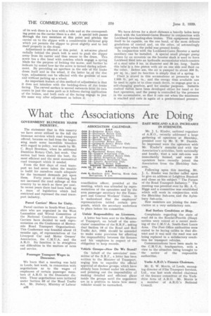
For use with the Lockheed-Gates Booster, as well as for other applications, the Lockheed Company has devised a two-leading-shoe brake of considerable merit. It is, of course, hydraulically operated either directly by Lockheed wheel cylinders or by means of the Lockheed Bisector device. In each case there are two expanding units to the drum, one at each end of the shoes.
The exterior of the casing of this unit is cylindrical and forms the pivot bearing with, incidentally, a generous area. Bearing on it is a corresponding concave cylindrical surface formed at the ends of members called shoe carriers. When the brake pedal is pressed the expander plungers move apart in both units. They are given a certain amount of float with relation to the expander housing, however. Consequently the leading tip of each shoe carrier is forced away from that housing, but the trailing tip of each shoe carrier remains against the housing and pivots on it. The operation is therefore equally effective in both directions.
The shoe carriers are hollow, and each one has a slipper mounted symmetrically on it. This slipper is rather like an ordinary faced shoe with its ends cut away, but at the centre of its web there is a boss with a hole and at the corresponding point on the carrier there is a slot. A special bolt passes through the two members at this point and pitches the carrier on to the slipper with a considerable frictional grip which yet permits the slipper to pivot slightly and to bed itself properly in the drum.
Adjustment is effected at this point. A set-screw placed radially behind the pinch bolt is used to push the slipper away from its carrier and thus nearer to the drum. This screw has a disc head with notches which engage a. spring blade for the purpose of locking the screw, and further to indicate by sound how far the screw is turned during adjustment. By providing an aperture in the side of the brake drum itself and in the wheel, if the latter be.of the disc type, adjustment can be effected with the greatest of ease and without jacking up a wheel.
An important feature of this method of adjustment is that it does not interfere with the bedding-down of the brake facing. The curved surface is moved outwards from its own centre in just the same path as it follows during application of the brakes, and both ends of the facing engage in just the same way after adjustment as before it.
We have driven for a short distance a heavily laden lorry fitted with the Lockheed-Gates Booster in conjunction with Lockheed two-leading-shoe brakes. This equipment showed itself to be capable, on the one hand, of the most delicate gradations of control and, on the other, of astoundingly rapid stops when the pedal was pressed firmly.
In conjunction with the Lockheed-Gates Booster a useful auxiliary can be installed. A special small plunger pump driven by an eccentric on the booster shaft is used to force Lockheed fluid into an hydraulic accumulator which consists of a steel tube 3 ins, in diameter and 30 ins. long. Inside this tube' is a free piston with air on one side and fluid on the other.. Before use, the air is pumped to about 500 lb. per sq. in., and its function is simply that of a spring. Fluid is stored in this accumulator at pressures up to 1,000 lb. per sq. in., and the energy thus available can be used to open or to close coach doors, to engage gear in a self-changing gearbox, sind for similar purposes. Suitable control valees have been developed either for hand or for foot operation, and the pump is controlled by the pressure in the accumulator, so that it cuts out when the maximum is reached and cuts in again at a predetermined pressure.