


A LOW-LEVEL INDICATOR FOR LIQUIDS.
Page 28
If you've noticed an error in this article please click here to report it so we can fix it.
A Resume of Recently Published Patent Specifications.
-0 W. LANCHESTER., whose name so often appears in .12 .conneetion with new inventions, describes a new alarm or indicator which will inform the driver of the fact that his level of petrol or lubricating oil has fallen below a predetermined level, in specification No. 232,661.
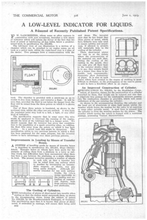
The left-hand view of our illustration is a section of a , chamber which can be attached to an engine sump, an oil tank or a petrol tank, whilst the right-hand view is a plan of the device. Two passages form a communication with the tank. The chamber is provided with a screw-cap so as to render it free from leakage, and contains a float. It will be seen that, provided the fluid is not below the danger level, the float will be raised from the three points on which it is shown resting.
One of these three points is insulated, as shown in the sectional view, whilst the other two are earthed. A wire from the insulated point may lead to a bell, a light, or any other kind of indicator.
The specification suggests that in some cases this wire might be employed to interrupt the running of the engine, should the level of the lubricant fall to a danger point. We should suppose that the inventor has given due consideration to the possibility of a spark occurring when, on refilling, the float lifts away from the points on which it has been resting. In a petrol tank this might be dangerous. The specification refers to two previous patents in which a float has been employed for the same purpose, but the inventor claims to have advantages over these previous patents.
Improvements in Loading by Means of Transfer Boxes. A SYSTEM of handling goods by means of transfer boxes
is described in specification No. 231,031, Hugo Christofoletti. Transfer boxes on wheels have been made for the purpose of rolling them from a platform to a lorry or railway truck, but difficulties have been encountered when there has been a gap between the platforms, or a slight difference in level. The present invention provides a number of wheels in each row, so that a transfer box can be rolled from one railway truck to another by interposing an intermediate support, as ' shown, any gap
being easily bridged. Although primarily intended for use with railway trucks, the idea seems applicable to the loading and unloading of commercial motors, both from railway trucks and platforms.
The Cooling of Cylinders.
THE introduction of pieces of sheet-metal into rnoulde when
casting so that the molten metal surrounds them, as shown in the accompanying views, forms the subject of patent No. 219.880, by the 1VIaechinenfabrik Esslingen, of Germany. The specification says that it is known that pieces of sheetmetal, if embedded in castings, will ensure their being solid B44 and dense. The inventor says that he has foiand that these pieces of metal, which have hitherto been only used to ensure solidity and soundnose, if allowed to project,' will materially help in the cooling of the cylinder.
These sheet-metal pieces are east in at the points where the cross-sections of the material are such that, during the cooling of the casting in the mould, they can only give off their heat to the exterior slowly; that is to say, they remain liquid for a longer time than is desirable, and, consequently, frequently show formations of pipes. It is also at such places where heat created in the course of working is most difficult to dissipate, so the prolongation of the cast-in pieces is said to have a beneficial effect in an engine.
An Improved Construction of Cylinder.
SPECIFICATION No. 232,831, by the Studebaker Corpo ration; of America, claims, for the construction of a cylinder described by them, that weight can be reduced and also that a relatively free passage for the combustible mixture passing into the combustion chamber is provided, which will cause turbulence of the gas entering the cylinder.
As shown in the accompanying drawing, the cylinder and the head are of aluminium or some light metal, whilst the member which forms the seating for the valve is of cast-iron or some other suitable metal. A steel liner is pressed into the cylinder to form the wearing surface for the piston. The member which carries the valves is formed with a restricted passage, possessing Venturi characteristics.