A NEW FORM OF CHANGE-SPEED GEAR.
Page 23

If you've noticed an error in this article please click here to report it so we can fix it.
A Worm which Engages Any of Three Separate Worm Wheels Giving Three Different Gear Ratios. How Thrusts are Provided For.
WE have recently had an opportunity of inspecting a new form of change-speed gear, which is contained entirely in the differential box on the back axle. Many attempts have been made to design a satisfactory gear of the kind, in which the usual change-speed gearbox is dispensed with. The gear in question is the invention of Mr. T. S. James, of 28, Sandleigh Road, Leigh-on-Sea, Essex. Mr. James is no new hand at inventing., for many of his inventions and improvements are in daily use in thousands of homes and
• factories.
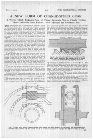
The main object of the present invention is to provide a change-speed gear in which a direct drive is obtained on every gear, excepting the reverse. The principle of the worm drive is maintained in this gear, but the application of it contains many novel points. ..ks will be seen from the illustration in Fig. 1, there are two discs, which lie parallel to each other and at a sufficient distance apart to allow of the introduction of a worm between them as shown. On the• inner faces of these discs rings of teeth of special form are provided, which are suitable for engagement with the special worm employed.
It will be seen that the two larger rings of teeth are not formed integral with the disc, but are fitted into grooves :formed in the face of the latter, being provided with helical springs, which lie at the back of the rings of teeth. A number of these springs is fitted in each groove, each one bearing against au abutment in the groove and a similar abutment on the back of the ring. By this means it is possible for each ring to have a slight rotary movement, independent of the discs—in other words, it forms a spring drive.
It has not been found necessary to embody this arrangement in the smallest of the rings of teeth, as this only comes into operation when the car is on the move. These discs are mounted on the ordinary differential box, the surroundings of which are as usual.
Reference to the right-hand sectional view (Fig. 1) will show that there is sufficient space between the rings of teeth for the worm to get• clear of one ring before engaging the next.
The left-hand view (Fig. 1) shows the positions of the worm as it is raised or lowered to enable it to engage the different rings of teeth. It will be seen that the worm shaft
does not move in parallel lines, but swings on the universal joint behind the flywheel as a pivot. It is obvious, were the worm of ordinary form, that there would be a tendency for it to force the two side plates apart, and it would be hardly possible to construct plates of sufficient strength to withstand this spreading tendency, unless they were unduly heavy. To overcome this difficulty Mr. James has designed a special form of worm, in this the faces which engage when driving are slightly undercut as shown in Fig. 2. The effect of this is slightly to draw the plates towards each other and into deeper engagement with the worm rather than to force them apart. The buttress form of tooth is also designed to make engagement of the worm and rings of teeth easier. The inventor has chosen the appropriate name of "the dual drive" for his contrivance, The close-up view in Fig. 2 is a section taken through the centre of the worm. A separate reverse box of simple construction is provided.
A company has been formed to develop commercially this invention and the whole of the foreign patents.
We understand that Mr. James has still further developments of direct drive by means of a worm, hut in a different form ; details of these, however, are not available.


