LARGER LOADS on a Popular Chassis
Page 51

If you've noticed an error in this article please click here to report it so we can fix it.
WITH so robust a chassis as the model AA Ford there is, to some users, always a temptation to overload it, whilst others find need for a larger body space. The chassis may be converted to take a greater pay-load, the wheelbase may be extended, or both may be done to work in conjunction. Any of these courses avoids maltreatment of the standard vehicle and, in the long
run, saves money.
Dealing first with the
method of extending the wheelbase and loading space according to the design of A. Ferraris, Ltd., 200-220, The Broadway, Crieklewood. The wheelbase may be increased by 1 ft., 2 ft. or 3 ft., giving respectively 12 ft., 13 ft. and 14 ft. for this dimension ; the hodY spaces then become 10 ft. 6 ins., 11 ft. 6 ins. or 12 ft. 6 ins. to 13 ft. The chassis weights of the three types are 1 ton 3 cwt., 1 ton 3i cwt. and 1 ton 4 cwt. respectively. The prices of the chassis at the London works are 1225, £230 and
£235 respectively. All these vehicles come within the 125 tax category, as the unladen weight of each with its body exceeds 30 cwt. but not 2 tons.
The process, of increasing the length of the vehicle is carried out by moving the springs, rear axle, propeller shaft and radius rods backwards to the extent of the increase in the wheelbase. The forward end of the propeller shaft takes its bearing in a housing bolted to a special girder member mounted between the frame channels by means of two TJ-bolts on each side. The brackets carrying the girder are designed to permit accurate alignment coupled with
easy assembly. An additional short shaft is employed between the rear end of the gearbox and the -original propeller shaft. The forward end of the torque tube is carried in a steady bearing, and there are two universal joints in the transmission-shaft line in place of the original one.
The frame is altered by cutting away that portion behind a line 3 ft. 5i ins. to the rear of the driver's cab and Tikins. behind the arched cross-member a the original Ford frame.
To form the new extended frame a 5-in.-deep channel member is riveted to the frame on each side, there being an overlap of 1 ft. fif ins, to ensure adequate strength at the junction of the old and new frames. Behind this point there are two channel-steel crossmembers provided with gussets. Rivets are used throughout the construction. The extended frame is flat in elevation throughout its entire length and the side members run parallel to each other from a point approximately in line with the arched cross-member. The height of the frame from the' ground is 2 ft. 6 ins, when loaded, and the frame flanges are 3 ins. wide., Either the extended-frame types or the 24on LoadMore can be provided with the standard or dual-ratio transmission systems. For those who require to carry two tons net of goods the Ferraris LoadMore is available. This also comes under the .125 tax rating. The frame may be of the standard length but fitted with dual rear springs of the type described hereafter, or the chassis may be extended by 1 ft. or 2 ft. in conjunction with the springs in question. The prices are as follow :—Standard wheelbase, £245; with 1-ft. extension, £250; with 2-ft. extension, 1255. Extra items for this type of chassis comprise N.A.P. tyres, £15: heavyduty pneumatic tyres, £15; or giant tyres and wheels, £25.
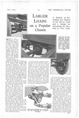
The main item of interest in the Load-More conversion set is the , double-semi-elliptic suspe 11'1 i o n system. Both front and rear ends of the springs are connected to stout cast-steel brackets bolted to the frame side members. These brackets form the supports for large pivot pins upon which oscillate two forked members, one forming the shackle for the upper spring and the other that for the lower one. The springs have nine leaves each, the width being 2 ins. At their centres they are mounted in the manner shown.


