 1
1 2
2 3
3 4
4 5
5 6
6 7
7 8
8 9
9 10
10 11
11 12
12 13
13 14
14 15
15 16
16 17
17 18
18 19
19 20
20 21
21 22
22 23
23 24
24 25
25 26
26 27
27 28
28 29
29 30
30 31
31 32
32 33
33 34
34 35
35 36
36 37
37 38
38 39
39 40
40 41
41 42
42 43
43 44
44 45
45 46
46 47
47 48
48 49
49 50
50 51
51 52
52 53
53 54
54 55
55 56
56 57
57 58
58 59
59 60
60 61
61 62
62 63
63 64
64 65
65 66
66 67
67 68
68 69
69 70
70 71
71 72
72 73
73 74
74 75
75 76
76 77
77 78
78 79
79 80
80 81
81 82
82 83
83 84
84 85
85 86
86 87
87 88
88 89
89 90
90 91
91 92
92 93
93 94
94 95
95 96
96 97
97 98
98 99
99 100
100 101
101 102
102 103
103 104
104 105
105 106
106 107
107 108
108 109
109 110
110 111
111 112
112 113
113 114
114 115
115 116
116 117
117 118
118 119
119 120
120 121
121 122
122 123
123 124
124 125
125 126
126 127
127 128
128 129
129 130
130 131
131 132
132 133
133 134
134 135
135 136
136 137
137 138
138 139
139 140
140 141
141 142
142 143
143 144
144 Eliminating fatigue failure by tank design
Page 55
If you've noticed an error in this article please click here to report it so we can fix it.
3y G. Cannon, chief engineer, tank division, Crane Fruehauf
— AA.5454 which combines high nechanical properties with good formability aid excellent welding characteristics. .
Elliptical sections provide the best ialance between strength, weight,' Toss-sectional area, and ease of :onstruction. The smooth change of contour if the circumference ensures that nanufacturing processes do not set up 4h-stress areas. Although the elliptical action is preferred, it does not exclude the tse of the larger area sections if the allowing conditions are met. Very small adial sections should be avoided as these an cause problems when internal heads are nartufactured requiring extreme stretching if the material in two planes and also cause ocalized areas of rigidity in the tank shell. Tery large radial sections should also be ivoided as the shell sheets become very nuch flatter and weaker, producing ;onditions that encourage fatigue failures.
Having decided upon the material and hape of the tank shell it is important that hese values, which are the basis for the ;alculated strength of the tank, are naintained. It would appear that once laving selected a material it could then be ;onsidered a constant factor. However, nanufacturing operations can radically &feet material properties. The rolling and 'orming of shell sheets causes workiardening to occur. This causes progressive ncreases in both ultimate and proof stresses 'rid a decrease in formability. While some degree of work-hardening is unavoidable, and even desirable, an excessive degree is dangerous in that the material loses its flexibility.
The other major factor affecting the material is welding. The heat applied to the weld seam tends to anneal the material in that area reducing the strength. To reduce the amount of heat at the weld seam, specially designed automatic welding equipment is used for all longitudinal seams ensuring smooth, full penetration welds of maximum strength in a single operation.
Further considerations made to reduce the number of welds and reduce distortion include the use of maximum-size shell sheets (up to 20ft long); the rolling of sheets to close tolerances to reduce fit-up distortions; and extra thickness shell sheets along the underside (where most welding occurs) to absorb the heat produced and reduce distortion.
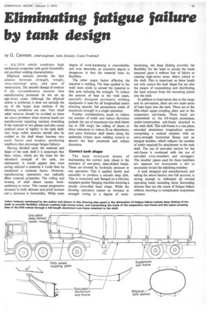
Correct tank shape
The main structural means of maintaining the correct tank shape is the inclusion of one-piece, deep-dished heads. These are formed by hydraulic pressure in one operation. This is applied slowly and smoothly to produce a smooth deep dish. This is contoured and flanged on a full-size, template-guided flanging machine ensuring a closely controlled head shape. While the forming operation causes an increase in•strength owing to a degree of work
hardening, the deep dishing provides the flexibility for the head to accept the loads imposed upon it without fear of failure or causing high-stress areas where joined to the shell. This is important as these heads not only assure the tank shape but are also the means of transmitting and distributing the load stresses from the mounting points into the shell.
In addition to load inputs due to the cargo and its movement, there are two main areas of load input into the tank. These are at the fifth-wheel upper-coupling plate and at the suspension sub-frame. These loads are transmitted to the full-length, aluminium, under-construction sub-frame attached to the tank shell. This sub-frame is a one-piece, extruded aluminium longitudinal section comprising a vertical member• with an extra-strength horizontal flange and an integral doubler, which reduces the number of welds required for attachment to the tank shell. The use of extruded section for the sub-frame is continued with the use of extruded cross-members and outriggers. The doubler plates used for these members are separate but incorporate a slot to accurately locate the adjoining member.
A tank designed and manufactured, and taking the above factors into full account, is strong enough to withstand all normal operating loads including those fluctuating stresses that are the cause of fatigue failure without resorting to complicated suspension systems.