


Advancing Injection Pumps When Idling
Page 88
If you've noticed an error in this article please click here to report it so we can fix it.
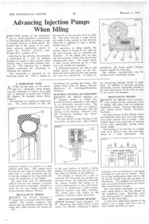
INJECTION pumps of the distributor • I type in which „regulation is performed by throttling the intake are prone to give a retarded injection at idling Speed. To prevent this is the object of an automatic advance mechanism shown in patent No. 879,531. (C.A.V., Ltd., WarpIe Way, London, W.3.) Referring to the drawing, the pumping is performed by a pair of opposed plungers (1) which, as they revolve, make contact with a four-lobed internal camring (2). The cam-ring has a limited angular movement for advancing or retarding the injection.
' This movement is imparted by an hydraulic piston (3). This is subject at the end (4) to fuel pressure from an inlet (5). The other end has a larger piston (6) which is also subject to fuel pressure when this is sufficient to open a springloaded valve (7) In operation, at idling speeds, the smaller piston is moved to the right by the fuel pressure and so advances the injection. As the speed rises, so does the fuel pressure, which then unseats. the spring-loaded valve. The larger piston is thus forced leftwards pp to a stop face, and retards the injection.
A continued pressure rise, due to still higher speeds, acts again on the lefthand end and readvances the cam against the force of a spr:ng (-3). In these cir cumstances, the larger pistOn reinains" inactive against its stop face_ The advance characteristics can be varied to suit a particular engine.
• A SEMI-SOLID TYRE
A TYRE having some of the advan
tages of a pneumatic whilst possessing the resistance to failure of a solid tyre is disclosed in patent No. 879,525. (H. Bugden, 90 Conway Street, Hove, Sussex.) The drawing is a section of wheel and tyre. The novel feature is that the
innermost member (I) consists of a thin resilient steel tube. The rubber tread (2) and the side walls are bonded to this tube, also to a steel Mounting ring (3). A web (4), welded to the ring, forms the means of attachment to the wheel.
The steel liner• may be additionally inflated and for this purpose a conventional tyre valve is provided. Mention is made of the tyre being suitable for house-to-house delivery vehicles.
HEAVY-DUTY WHEEL
PATENT No. 878,784 discloses a design for a cast-steel wheel for heavy vehicles. The casting comprises hub, spokes and an abutment surface for the brake disc. Ribs between the spokes arc
p30
fan-shaped for cooling the brake. The patent comes from H. Klaue,Christopherstrasse 19, Uberlingen/Bodensee, Germany.
ELECTRIC CONTROL OF INJECTION DATENT No, 880,072 describes an
injection system in which prepressurized fuel is admitted to the engine by an electrically operated valve. The advantage claimed is that very accurate control of the commencement and the timing can be obtained. (Weselco, Ltd., 320 Permanent Building, Bay Street, Toronto, Canada.) The unit shown in the drawing is the electrically operated valve, This is shown in the open pbsition in which a sliding planger (1) connects the fuel inlet (2)to the outlet (3) leading to the injectors.
The plunger is moved by a pair of solenoids (4). One pulls the• plunger'up, the other down.By using two solenoids, the scheme enables the timing to be varied electronically to suit such conditions as air temperature, intake suction, injection pressure and other variables. The patent gives full details of the circuitry involved in these operations.
DIE-CAST CYLINDER 'BLOCKS
FROM National Lead Company; 1 l 1 Broadway, New York, U.S.A., comes patent No. 883,441, diseloSing a scheme
for .die-casting cylinder .blocks in light alloy. In addition to the high accurapY _obtainable, another advantage claimed.is the total elimination. of the risk ',of sand in the cast-in oil passages.
HEAVY-DUTY BOGIES
PATENT No.. 880,064 -refers to .heavy: duty bogies having numerous •pairs of wheels and deals with an hydraulic suspension 'system. (Cranes (Dereham), Ltd., South Green Works. Dereham, Norfolk.)
The main feature of the scheme is that the hydraulic rams that carry the frame have their pistons free to rotate. This enables them to be used also as steering pivots, thus appreciably cutting down frame height.
The drawing is an end view of a bogie such as is used to carry the swan-neck beam of a large semi-trailer. The
hydraulic rams are shown at 1, one being provided for each pair of wheels. They are of the displacement type, that is, the oil can be moved from the top space to the bottom. The cylinders are stationary and are mainly housed inside the frame, thus economizing in height.
• The dual-wheel assemblies are steerable, being fixed. to thefree pistons of the suspension rams. Hydraulic jacks are incorporated to stabilize the crossbeam of the swan neck.
A particular 'application quoted in the patent is to a bogie with four rows of four wheels steerable in pairs.