


Patents Completed.
Page 22
If you've noticed an error in this article please click here to report it so we can fix it.
Complete specifications of the following patents will be sent to any address in the United Kingdom upon receipt of eightpence per copy at the Sale Branch, Patent Office, Holborn, W.C.
WRENCH.--Blanc.—No. 7,397, dated 24th March, 1910.—According to this invention, an adjustable wrench is formed of a body piece, upon which is hinged a handle and one of the jaws. On the body piece a flat is formed to engage one side of the nut, and the movable jaw is arranged so as to bear upon only a small portion of the face of the nut, not near the edge. The flat jaw is held up against, the nut, and as the handle is turned it engages one end of the lever forming the second jaw. This forces the jaw into contact with the second face of the nut and locks it as long as pressure is applied to the handle, thus allowing the nut to be unscrewed.
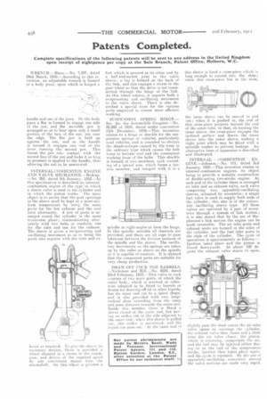
INTERNAL-COMBUSTION ENGINE AND VALVE MECHANISM.—Redrup. —No. 291, dated 5th January, 1910.—In this specification is described an internal. combustion engine of the type in which a sleeve valve is used in the cylinder and in which the piston works. The main object is to secure that the port openings in the sleeve shall be kept at, a more-uniform temperature by using the same ports for the hot exbaust and the cool inlet alternately. A row of ports is arranged round the cylinder in the same transverse plane; communicating alternately with two belts or conduits, one for the inlet and one for the exhaust. The sleeve is given a reciprocating and oscillating movement so as to bring the poets into register with the inlet and ex
haust as required. To give the sleeve its necessary motion, there is provided a wheel situated in a recess in the crankcase, and driven at the required speed by A fly convenient means from the crankshaft. On this wheel is pivoted a
link which is t,ecured at its other end by a ball-and-socket joint to the valve sleeve • a lug is formed on the back of the link, and this engages a recess in the gear wheel so that the drive is not transmitted through the hinge of the link. As this wheel rotates, it imparts both a reciprocating end oscillating movement to the valve sleeve. There is also deecribed a special form for the various ports employed to ensure more efficient working.
SUSPENSION SPRING HINGE,Soc. Art. des Automobile Gregoire.—No. 28,883 of 1910, dated under convention 15th December, 1909.—This invention relates to a hinge or shackle for the suspension springs of vehicles, particularly road vehicles, and is intended to obviate the disadvantages caused by the wear in the ordinary type which causes the bolt holes to become oval and the consequent working loose of the bolts. This shackle is formed of two members, each consisting of A lateral arm, which forms a tension member, and integral with it is a
spindle at right-angles to form the hinge. In this spindle, suitable oil channels are provided, and there are oil cups to pass lubricant between the friction surfaces of the spindle and the sleeve. The oscillatory movements oti the springs are take ii up by the roller or sleeve on the spindle as it is capable of rotation. It is claimed that the component parts are suitable for very cheap production.
DRAW-OFF COCK FOR BARRELS. --Nicholson and Hill.—No. 4534, dated 23rd February, 1910.—This valve or cock ecnsists of two main parts, of which the outer body, which is screwed or otherwise adapted to be fitted to barrels or drums for drawing off oil or other liquids, has its inner end cut to a spiral shape, and is also provided with two longitudinal slow extending from the inner end some distance towards the outer end. Inside this member there' is fitted a slecve closed at the outer end, but having an Orifice cut in the side adjacent to the outer end ; when this sleeve is pulled out, One orifice is uncovered, and the 1:qtlid can pass out At the inner end of
this sleeve is fixed a cross-piece which is long enough to extend into the slots; when this cross-piece lies in the slots, the inner sleeve can be moved in and out; when it is pushed in, the end of this, cross-piece projects beyond the end of the outer tulle, so that, on turning the inner sleeve, the cross-piece engages the inclined surface and draws the inner sleeve into the outer sleeve, making a tight, joint which may be fitted with a suitable washer to prevent leakage. An alternative form of apparatus is described and illustrated.
INTERNAL COMBUSTION ENGINE.—Johnson.—No. 111, dated 3rd January, 1910.—This invention relates to internal-combustion engines, its object being to provide a suitable construction of double-acting two-stroke engine. At each end of the cylinder there is arranged an inlet and an exhaust valve, each valve comprising two oppositely-oscillating sleeves, actuated by eccentrics ; a single fuel valve is used to supply both ends of the cylinder ; this also is of the concentric oscillating sleeve type. All these valves are operated by a pair of eccentrics through a system of link motion; it is also stated that by the use of Stephenson's link motion the engine can be made reversible. The air inlet ports and exhaust ports are formed in the sides of the cylinder, and the fuel inlet ports in the ends of the cylinder. The cycle of operations is approximately as follows:— Ignition takes place and the piston is forced downwards. At about 120 degrees the exhaust valve starts to open,
slightly past the dead centre the air-inlet valve opens to ;cavenge the cylinder, the exhaust valve then closes and a little later the air valve closes the piston, which is returning, compressAs the air, and the fuel may be injected either during or at the end of the compression stroke, ignition then takes place again. and the cycle is repeated. By the use of oppositely-oscillating concentric sleeves the valve motions are made very rapid.