


Power-assisted Steering Gear
Page 62
If you've noticed an error in this article please click here to report it so we can fix it.
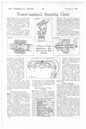
AS'riehicles tend to be made larger and heavier, their operation sometimes calls for more effort than can be supplied by human agency, and for this reason the power-assisted steering mechanism shown in patent No. 493,936, by Manly Corporation, 250, West 54th Street, New York, U.S.A., is of particular interest.
It is a vital necessity, in a scheme of this nature, .that, in the event of power failure, the mechanism remains manually operative, and the design is based on this requirement. The draw ing shows a steering gear having the conventional components, with the addition of a double-acting hydraulic cylinder, the piston of which is connected to the wormwheel sector (1). The sector is assembled in its bearings with a small amount of endplay, through which it is moved when the worm is turned. The end-play serves to operate a rocking bar (2) which moves a slide valve (3) ; this constitutes the hydraulic control for admitting fluid to the cylinder.
When the sector has moved hydraulically, it exerts a thrust on the worm; this reverses the end-play owing to the slope of the teeth, and recloses the fluid valve. Should the power fail, the gear can still be operated manually, although, naturally, increased effort is required.
Coil-spring Universal Joint.
ltfiANY attempts have been made to AV./produce a constant-velocity universal joint, and patent No. 494,057 shows a device of this nature in which the resilient coupling member is a helical spring. The patent conies from R. Dome, 6 Szabolcs-u., V. Budapest, Hungary, and another.
The joint comprises a pair of flanges connected by .a stout helical spring (1). One flange has an extension into the centre of the spring, in the form of a tubular housing (4) ; the other flange carries a nose (3) which is a sliding fit in a self-aligning roller bearing (2). This acts, merely, as a ball joint for centring the two flanges, there being no relative rotation other than that caused A36
by the flexing of the helical spring.
Another scheme is described in which the roller bearing is replaced by a pair of rubber rings approximating to a hemispherical form.
Improved Control of Torque Converters.
PATENT No. 494,269, deals with a clutching system for a torque converter, the object being -to incorporate a direct drive for top-gear conditions, with an automatic change-over to the
converter when a lower ratio. is required. The patentee is Allgemeine Elektricitats-Gesellschaft, 2-4 Friedrich Karl-Ufer, Berlin, Germany. An arrangement of this nature, if controlled solely by engine speed, is liable to cause a change to a lower gear at unwanted times, and the invention is directed towards providing a control more suited to road conditions.
The engine shaft (7) is connected, via a splined slider (6) to the primary membet (8) of the torque converter. The output shaft is keyed to the secondary member (4) and extends to a plate clutch (5) which, by movement of the slider (6), can establish a direct drive.
A centrifugal governor (3) is linked to the clutch slider (6) and controls its engagement, in accordance with engine speed. This action is modified, however, by the strength of the governor spring being varied by a lever (1), which is moved by a cam (2) on the accelerator. pedal. This enables the direct drive to remain engaged at low engine speeds occasioned by throttling.
Built-up Manifolds.
THE usual cast manifold is a corn. plex piece of work and is, generally, much heavier than need be, such excess weight being due entirely to foundry conditions and in no way necessary to the working of the unit. A scheme for building a manifold from welded, sheetmetal pressings is shown in patent No. 493,619, by S. Smith, Dingley Dell, Chobham, Surrey.
From the drawing it will be seen that the main pressing is drawn down to form a passage (6) and a double-width centre passage (4), whilst a third passage (2) consists of a short tube welded in. These three branches are welded on to a hack plate, which is bossed for bolting on to the engine. The inlet pipes (5) are made of copper and are welded to the back place ; they are connected by a heated stabilizer tube (1) which, in this case, is for the balancing of two carburetters. The point of attachment of the exhaust pipe is the welded-on flange (3).