


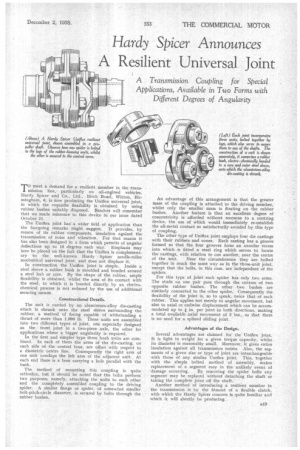
Hardy Spicer Announces A Resilient Universal Joint
Page 53
If you've noticed an error in this article please click here to report it so we can fix it.
trans
mission line, particularly on oil-engined vehicles, meet a demand for a resilient member in the Hardy Spicer and Co., Ltd., Birch Road, Witton, Bir mingham, 6, is now producing the Uniflex universal joint, in which the requisite flexibility is obtained by using rubber bushes suitably disposed. Readers will remember that we made reference to this device in our issue dated October 21.
The Uniflex joint has a wider field of application than the foregoing remarks might suggest. It provides, by reason of its rubber components, insulation against the transmission of noise and vibration. For that reason it has also been designed in a form which permits of angular deflections up to 15 -degrees each way. Emphasis may here be placed on the fact that the Uniflex is complementary to the well-known Hardy Spicer needle-roller mechanical universal joint, and does not displace it.
In construction the Uniflex joint is simple. Inside a steel sleeve a rubber bush is moulded and bonded around a steel hub or core. By the shape of the rubber, ample flexibility is obtained, whilst the area of its contact with the steel, to which it is bonded directly by an electrochemical process is not reduced by the use of additional securing means.
Constructional Details.
The unit is carried by an aluminium-alloy die-casting which is shrunk onto the steel sleeve surrounding the rubber, a method of fixing capable of withstanding a thrust of more than 1,000 lb. These units are assembled into two different types of joint, one especially designed as the front joint in a two-piece axle, the other for applications where a bigger angularity is required.
In the first and simpler type three bush units are combined. In each of them the arms of the die-casting, on each side of the central boss, are offset with respect to a diametric centre line. Consequently the right arm of one unit overlaps the left arm of the adjacent unit. At each end there is a boss carrying a hole parallel with the bush.
The method of mounting this coupling is quite orthodox, but it should be noted that the bolts perform two purposes, namely, attaching the units to each other and the completely assembled coupling to the driving spider. A similar flange or spider, of somewhat smaller bolt-pitch-circle diameter, is secured by bolts through the rubber bushes. An advantage of this arrangement is that the greater mass of the coupling is attached to the driving member, whilst only the smaller mass is floating on the rubber bushes, Another feature is that an excellent degree of concentricity is afforded without recourse to a centring device, the use of which would immediately re-establish the all-metal contact so satisfactorily avoided by this type of coupling.
The other type of Uniflex joint employs four die castings with their rubbers and cones. Each casting has a groove formed so that the four grooves form an annular recess into which is fitted a steel ring which ,serves to locate the castings, with relation to one another, near the centre of the unit. Near the circumference they are bolted together in much the same way as in the three-unit joint, except that the bolts, in this case, are independent of the spiders.
For this type of joint each spider has only two arms, The studs on one pair pass through the centres of two opposite rubber bushes. The other two bushes are similarly connected to the other spider. Consequently the flexibility of the joint is, so to speak, twice that of each rubber. This applies not merely to angular movement, but also to axial or endwise displacement which can be accommodated up to 4 in. per joint in both directions, making a total available axial movement of 2 ins., so that there is no need for a splined sliding joint.
Advantages of the Design.
Several advantages are claimed for the Uniflex joint. It is light in weight for a given torque capacity, whilst its diameter is reasonably small. Moreover, it gives entire insulation against all transmission noises. Also, the segments of a given size or type of joint are interchangeable with those of any similar Uniflex joint. This, together with the simple bolted method of assembly, makes replacement of a segment easy in the unlikely event of damage occurring. By removing the spider bolts any segment may be replaced without detaching the shaft or taking the complete joint off the shaft.
Another method of introducing a resilient member in the transmission is by the fitment of a flexible clutch, with which the Hardy Spicer concern is quite familiar and which it will shortly be producing.