


OIL-ENGINE
Page 46
Page 47
Page 48
Page 49
If you've noticed an error in this article please click here to report it so we can fix it.
-GOVERNING ;P:1
UMA TIC AND MECHANICAL
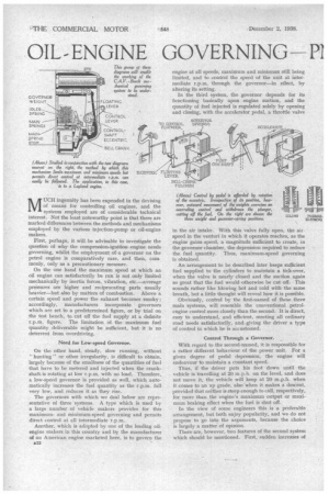
MUCH ingenuity has been expended in the devising of means for controlling oil engines, and the systems employed are of considerable technical interest. Not the least noteworthy point is that there are marked differences between the methods and mechanisms employed by the various injection-pump or oil-engine makers.
First, perhaps, it will be advisable to investigate the question of why the compression-ignition engine needs governing, whilst the employment of -a governor on the petrol engine is comparatively rare, and then, commonly, only as a precautionary measure.
On the one hand the maximum speed at which an oil engine can satisfactorily be run is not only limited• mechanically by inertia forces, vibration, etc.—average pressures are higher and reciprocating parts usually heavier—but also by matters of combustion. Above a certain speed and power the exhaust becomes smoky ; accordingly, manufacturers incorporate governors which are set to a predetermined figure, or by trial on the test bench, to cut off the fuel supply at a definite r.p.m. figure. The limitation of the maximum fuel quantity deliverable might be sufficient, but it is no deterrent from overdriving.
Need for Low-speed Governor.
On the other hand, steady, slow running, without " hunting " or other irregularity, is difficult to obtain, largely because of the smallness of the quantities of fuel that have to be metered and injected when the crankshaft.is rotating at low r.p.m. with no load. Therefore, a low-speed governor is provided as well, which automatically increases the fuel quantity as the r.p.m. fall very low, and reduces it as they rise.
The governors with which we deal below are representative of three 'systems. A type which is used by a large number of vehicle makers provides for this maximumand minimum-speed governing and permits direct control at all intermediate r.p.m.
Another, which is adopted by one of the leading oilengine makers in this country and by the manufacturer of an American engine marketed here, is to govern the in the air intake. With this valve fully open, the airspeed in the venturi in which it operates reaches, as the engine gains speed, a magnitude sufficient to create, in the governor chamber, the depression required to reduce the fuel quantity. Thus, maximum-speed governing is obtained.
An arrangement to be described later keeps sufficient fuel supplied to the cylinders to maintain a tick-over, when the valve is nearly closed and the suction again so great that the fuel would otherwise be cut off. This sounds rather like blowing hot and cold with the same breath, but a little thought will reveal how it is possible.
Obviously, control by the first-named of these three main systems, will resemble the conventional petrolengine control more closely than the second. It is direct. easy to understand, and efficient, meeting all ordinary road needs satisfactorily, and giving the driver a type of control to which he is accustomed.
Control Through a Governor. _ With regard to the second-named, it is responsible for a rather different behaviour of the power unit. For a given degree of pedal depression, the engine will endeavour to maintain a constant speed.
Thus, if the driver puts his foot down until the vehicle is travelling at 20 m.p.h. on the level, and does not move it, the vehicle will keep at 20 m.p.h. when it comes to an up grade, also when it makes a descent, provided that neither is steep enough to call, respectively, for more than the engine's maximum output or maximum braking effect when the fuel is shut off.
In the view of some engineers this is a preferable arrangement, but both enjoy popularity, and we do not propose to go into the arguments, because the choice is largely a matter of opinion.
There are, however, two features of the second system which should be mentioned. First, sudden increases of fuel are avoided, because the governor ensures a small time lag between quick depressions of the pedal and
movement of the control plunger. Secondly, if the engine be employed for other purposes than propelling the vehicle:—for generating electric current, winching or pumping, for instance—then the fact that it is governed to run at any desired speed enables the driver to set the control appropriately and calls for no further provision against fluctuations of the load on the dynamo, winch, cable, or whatever the engine be driving.
Turning now to the pneumatic system, the attractions here are simplicity and lightness. It is of relatively recent introduction and has gained considerable ground —particularly for engines installed in vehicles in the 30 m.p.h. class where weight is of premier importance.
The fact that this system is standardized by at least two first-class engine builders is sufficient recommendation of its efficiency and reliability. However, we cannot see it entirely ousting the governors in which rods and links afford positive actuation. A criticism sometimes lodged is that the variations of air velocity at low speeds canse fluttering of the diaphragm and that high-speed governing is sluggish. A further advantage is that if the air cleaner should become choked, fuel will be reduced in proportion.
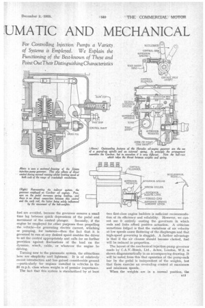
The layout of the mechanical injection-pump governor made by C.A.V.-Bosch, Ltd., Acton, London, W.3, is shown diagrammatically in an accompanying drawing. It will he noted from this that operation of the pump-rack bar by the pedal is independent of the weights, but that these exercise an overruling control at maximum and minimum speeds.
When the weights are in a normal position, the B I
bottom pin of the floating lever is its fulcrum, and rotation of the eccentric by the pedal controls the fuel quantity. When the pedal is hard down, however, (and, of course, at any other time) and the engine speed reaches its maximum (or minimum), the eccentric is the fulcrum. Another view—of the pump as installed by Leyland Motors, Ltd.—shows clearly the actual mechanism.
Now let us consider the action of the governor weights. These are held towards the spindle about which they revolve by three springs in each case. The three positions which they can assume are shown in a third diagram. The outermost spring is light and, unaided, holds the weight in the innermost position. It performs the function of governing at idling speed. At normal running speeds the combined pressure of -the three springs holds the weight in the second position shown. When maximum r.p.m. are reached, centrifugal force overcomes the triple spring pressure and the weight moves into the right-hand position, cutting off the fuel.
Simms Motor Units, Ltd., Oak Lane, East Finchley, London, N.2, uses on its injection pump a governor which falls in the
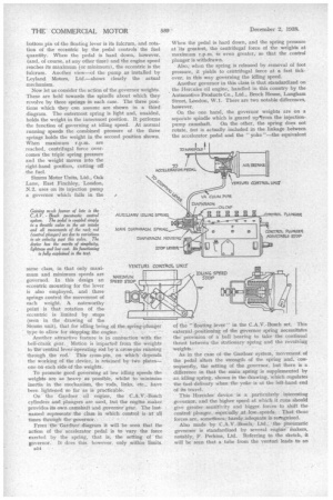
Gaining nrich favour of late is the C.A.V. Bosch pneumatic control system. The pedal is coupled simply to a throttle valve in the air intake and all movements of the rack rod (control plunger) are due to variations in air velocity past this valve. The device has the merits of simplicity, lightness and low cost. its functioning
is fully explained in the text.
same class, in that only maximum and minimum speeds are governed. In this design an eccentric mounting for the lever is also employed, and three springs control the movement of each weight. A noteworthy point is that rotation of the eccentric is limited by stops (seen in the drawing of the Simms unit), that for idling being of the spring-plunger type to allow for stopping the engine.
Another attractive feature is in connection with the bell-crank gear. Motion is imparted from the weights to the central lever-operating rod by a cross-pin running through the rod. This cross-pin, on which depends the working of the device, is retained by two plates— one on each side of the weights.
To promote good governing at low idling speeds the weights are as heavy as possible, whilst to minimize inertia in the mechanism, the rods, links, etc., have been lightened so far as is practicable.
On the Gardner oil engine, the C.A.V.-Bosch cylinders and plungers are used, but the engine maker provides its own camshaft and governor gear. The lastnamed represents the class in which control is at all times through the governor.
From the Gardner diagram it will be seen that the action of the accelerator pedal is to vary the force exerted by the spring, that is, the setting of the governor. It dces this, however, only within limits. MAXIMUM SPEED STOP
smgmiss
110!141)
1111=1111■11■JI
When the pedal is hard down, and the spring pressure at its greatest, the centrifugal force of the weights at maximum r.p.m. is even greater, so that the control plunger is withdrawn.
Also; when the spring is released by removal of foot pressure, it yields to centrifugal force at a fast tickover, in this way governing the idling speed.
Another governor in this class is that standardized on the Hercules oil engine, handled in this country by the Automotive Products Co., Ltd., Brock House, La.ngham Street, London, W.1. There are two notable differences, however.
On the one hand, the governor weights are on a separate spindle which is geared up•from the injectionpump camshaft. On the other, the spring does not rotate, but is actually included in the linkage between the accelerator pedal and the "yoke "—the equivalent of the "floating lever" in the C.A.V.-Bosch set. This external positioning of the governor spring necessitates the provision of a ball bearing to take the continual thrust between the stationary spring and the revolving weights.'
As in the case of the Gardner system, movement of the pedal alters the strength of the spring and, consequently, the setting of the governor, but there is a difference in that the main spring is supplemented by an idling spring, shown in the drawing, which regalateS the fuel delivery when the yoke is at the left-hand end of its travel.
This Hercules' device is a particularly interesting governor, and the. higher speed at which it runs should give greater sensitivity and bigger forces to shift the control plunger, . especially at low. speeds. That these forces axe, sometimes, barely adequate is recognized.
Also made by C.A.V.-Bosch, Ltd.; the pneumatic governor is standardized by several engine Makers, notably, F. Perkins, Ltd. Referring to the sketch, it will be seen that a tube from the venturi leads to an air-tight chamber on the injection pump, one wall of which is formed by a leather diaphragm_ To the centre of this is attached the control plunger, and a spring tends to push it to the position for maximum fuel supply.
Closing of the throttle valve creates a depression in the chamber, compressing the spring and reducing the fuel " supply. With the throttle fully open, rising r.p.m., as was pointed out earlier, also cause suction on the diaphragm, so the valve both controls and governs.
It will be noted that there is a second spring within the first. This comes into play when the diaphragm has been drawn to the left-hand extremity of its travel, as at idling, with the valve closed. Then the inner spring comes up against a stop, and will cause the control plunger to move to the right, when the vacuum drops as a result of r.p.m. falling below the desirable minimum for idling.
The usual adjustments are provided, namely, for maximum and minimum throttle openings on the venturi unit, for maximum fuel delivery, at the right-hand end of the control plunger, and for idling, at the left-hand end. This last may be either of the screw-type as shown, or a quick-release cam, operated by a lever interconnected with the accelerator pedal so that it comes into• action only when the pedal is released and does not interfere with the fuel cut-off at maximum r.p.m.
A device is also provided, as in the other types of governor, for pulling the control plunger to. the extreme left, against the idling spring in order to stop the engine.