


PRACTICAL F,THODS OF MOUNTING THE SPARE WHEEL
Page 50
Page 51
Page 52
If you've noticed an error in this article please click here to report it so we can fix it.
WITII the advance in pneumatic tyre design, problems of stowing the spare wheel, like certain technical problems of our industry, call for more and more scientific attention. With small sizes of tyre it is not so much a question of weight or of handling difficulties, even when, as is general, tyres are mounted on stud-held wheels, the problem being one of the space occupied and of obtaining a secure fixing.
Except for vehicles engaged on farm and quarry work, there is no serious objection to the spare wheel being mounted under the rear end of the frame. Where, however, the risk of fouling banks, etc., is considered serious, probably the best position for the spare wheel is behind the cab, the weight being taken by the lorry floor. Some body space is occupied and the position is generally not possible rf tipping gear be fitted.
Most types of tipping gear for the lighter vehicles demand a clearance between the back of the cab and the front of the body, and in some cases it is possible to accommodate the spare wheel in this space, even if an inch or two must be robbed from the body length. Fixing devices offer no difficulty, and probably the best is a cross-bearer (with shaped cradle), resting on both frame longitudinals, to take the weight of the spare wheel, a clamp or strap on the back of the cab—preferably with padlock—holding it in position.
If this position proves riot to be practicable, the owner may have to choose between a door-side or bonnnet-side mounting—both of which are objectionable—and a mounting on the roof of the cab. For the latter position the cab must be built with a view to the load it has to carry.
Apart from the inconvenience of side mountings, they often impose stresses that are not too well provided for, although Leyland Motors, Ltd., has produced a straightforward and sturdy mounting by fixing a tube across the chassis, bolting it to both main longitudinal& In one example the tube slightly obstructs the floor of the cab adjacent to the seat, but there is n32
the advantage of strength anti reliability.
Heavier tyres, Weighing over 2 cwt. with rim or wheel, introduce other problems, principally that of ease of manipulation and that of obtaining a strong carrier which is not excessively heavy ; an under-frame carrier can weigh as much as 2 cwt.
in this class we may reckon high-pressure tyres of 40 ins. by 8 ins, and upwards, and the new low-pressure tyres of 9.75-in. section and upwards, although even smaller sizes Involve similar difficulties, and the prevention of rattle is common to all sizes, in particular, holdingdown nuts must be prevented from turning.
Urban buses usually carry no spare tyre, but coaches, alSo country buses, including doubledeckers, generally have to be so equipped. Under-tail mountings suit nearly all singledeckers, the problem becoming one of devising the best fixing, whilst in double-deckers there is the platform space under the stairway.
Under-tail carriers being suitable in so many cases for both passenger and goods vehicles, some of the better designs may be described. A strong fitting of the lighter type is employed on Bedford vehicles, this incorporating a V-shaped angle-iron platform, the forward—or open—end of which rests upon a cradle fixed below the frame. A swing bolt and wing nut support the rear end of the cradle, the nut having a countersunk seating to prevent it from slipping out of the slot.
A common A.E.C. mounting makes use of a threaded rod passing through the frame of the cradle, this being drawn up by a turnbuckle which cannot get loose, and this company has fitted a good many such carrienc: modified to enclose the spare wheel in a box. Such boxes can be rigid without being heavy and are often well worth while.
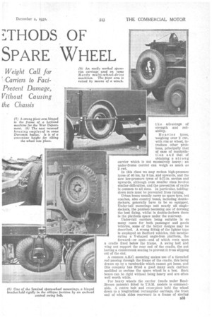
For heavy wheels the carrier (made under ReedBrown patents) fitted to T.S.M. models is commendable. A centre bolt and cross-piece hold the wheel down to a longitudinal rectangular carriage, the front end of which rides rearward in a frame of similar
shape, the frame resting on two transverse cradle members. The sliding carriage is held in the forward position by two hinged bolts, engaging with the rear cross-piece of the carriage.
Carrimore trailers have a similar mounting. In this case the sides of the sliding carriage sweep inward towards the rear, and the rear cradle member is given• lateral rigidity by having sloping sides rising from the width of the tyre outward to the width of the chassis frame.
A Leyland carrier of the sliding-frame type that is con
lidered good has a V-shaped carriage, the forward ends of which are suspended from two rollers, these resting on longitudinal rails mounted on the outer sides of the chassis frame members. The rails slope down to the rear.
A neat sliding and tilting carrier, with swing-bolt fastening in the centre, is emp,oyed on the Morris-Commercial Dictator chassis; an accompanying illustration shows how the roller rails are mounted.
On the Dennis Arrow passenger chassis the carriage moves sideways, a roller at the lower end supporting the weight on the ground. There is a special rattle-prevention device.
On goods vehicles it is often possible to find a convenient space for the spare wheel underneath one side of the frame between the axles, and if the carriage be secure and be balanced against a similar weight, such as the batteries, on the other side, there is no objection. A strong mounting of this kind has been used on Armstrong-Saurer Dauntless chassis, the trye resting in a cradle below the franse and
being held in an oblique position to an outrigger. Even this arrangement, we understand, is to be improved upon. For the really heavy tyres, such as those of 13.5-in. seelion, which, with rims or wheels, weigh from 3i cwt. to 4 ewt., plainly it is a good thing to eliminate the cradle altogether, because of its inevitable weight. It is a distinct advantage if the spare rim and tyre can rest on the frame, instead of hanging beneath it, but such an arrangement is dependent upon frame height and the class of bodywork. A bold effort has been made in regard to the big Met'cedesBenz vehicles. Fortunately, the frame height is such that, with the tyre standing against the tail end, it is convenient to lift the lower edge, using the frame cross-member as a pivot. The difficulty does not end there, however, for body supports are necessary for the whole length of the chassis, although there is sufficient depth between the frame and the 1834 body cross-bearers for the accommodation of this large tyre.
A solution has been found by resting the cross-bearers on deep runners, mounting the latter (behind the bogie) on frame outriggers instead of directly on to the frame members. This gives the necessary width of 4 ft. The heavy carrier is eliminated, likewise the risk of damage when backing into a bank.
To reduce considerably the effort of handling these heavy tyres, the Thorn ycroft concern has evolved a carrier under patent No. 352,223. Hinged to the frame side member is a plate, to which is bolted at a point eccentric to the wheel centre another plate, having a centre-bolt wheel mounting. Below this the spare wheel normally hangs in a horizontal position, being steadied by a bracket pendent from the off side frame member. After withdrawing a spring-loaded bolt, it is possible to turn the wheel about its eccentric mounting, so that it protrudes considerably at the side (IT the? frame, The carriage is then hinged upward into the vertical position, in which it is neatly held, and by further rotating the eccentric mounting the wheel is lowered to the ground.
For Foden vehicles, on which space is available behind the cab, a spare-wheel box is provided, this being divided diametrically in the vertical plane. The hinge is strong, so that, when one half of the box is lowered to the ground, the wheel is easily rolled in or out without causing strain.
An amidships mounting is employed on Sentinel steam wagons, two kinds being available. One necessitates the driver dragging the wheel from a flat position under the vehicle; but the other—somewhat resembling the Thornycroft carrier—eliminates this. It consists of a hinged plate fixed to the frame member, this normally carrying the wheel in an oblique position, in which it is held by menns of a swing halt. A good feature is that the wing nut carries a casing to enclose the bolt and keep the threads clean and lubricated. After dropping the hinged plate to the vertical position the wheel is easily lifted on or off.
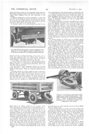
• The Duramin concern prbduces for six-wheeled meat carriers mounted on 13.5-in. tyres a housing comprising a circular frame that is fitted to the chassis within a recess on the near side of the body. The device is simple and, as in the Mercedes-Benz arrangement, success results from the fact that the heavy tyre and rim, when standing against the frame, can be lifted from its lower edge, pivoting conveniently
about the frame at a point each side of and, of course, higher than its lowest point.
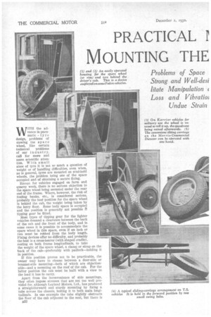
Certain carriers fitted to special vehicles for military and overseas use demand mention, because of their ingenuity. Some Earner vehicles, for example, have their spare wheels housed behind the cab. The wheel is centre-bolted to a pivot arm, its spindle carrying a pinion, so that it can be rolled up a quadrant-shaped rack. When in the vertical position the pivot arm is held; so that further rotation of the wheel causes the quadrant similarly to climb to its position behind the cab. On Albion vehicles also the rotation of the wheel is used to wind it into position.
Hardy multi-wheel-drive machines make use of hinged arms, raised by means of small hand winches that are accommodated on the back of the driver's cab, a similar device being used on some Leyland and Dennis machines.