


A CARBURETTER WITH INGENIOUS FEATURES.
Page 32
If you've noticed an error in this article please click here to report it so we can fix it.
A Résumé of Recently Published Patent Specifications.
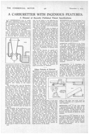
A N INTERESTING type of carbu/-Iretter, embodying several novel, useful, and ingenious features, is described in specification No. 214,266, by h'. Monier. It is actually an improvement on one which has already been patented, by the same inventor, and described by him in specification No 188,626.
The construction of this carburetter, and the method of its operation, may best be understood if reference be made to the accompanying drawing. It will be observed that it embodies the usual constant-level reservoir or float chamber with fuel inlet at the top, controlled by a needle, which closes as it moves up wards. In the drawing, which is, of course, only diagrammatic, the jet is shown as the constricted end of the pipe which conveys the fuel from the float chamber to the main body of the carburetter. The latter is in the form of a plain pipe, with its internal diameter tapering inwardly from the inlet end, which is at the bottom, to a point on the same level as the jet, and then outwardly until it equals that of the main induction pipe leading to the engine The throttle valve may be described as being roughly pear-shaped, and it is designed so that it can be elevated in the tapering part of the carburetter body until it closes the aperture_ An annular slit is cut in the carburetter at the narrowest part, and on the same level as the jet. The latter, it should he noted, is higher than the level of the fuel in the float chamber. Communication is established between the interior of the induction pipe and the float chain. her, by the pipe shown. Around the constricted part of the body of the carburetter an annular chamber is formed, and this also communicates with the interior of the induction pipe by means of a by-pass.
The operation of the carburetter is as follows :—When the engine is running normally, with the throttle valve open, the fuel is acted upon by the differential pressure (the difference 'between that in the float chamber and that at the end of the jet), and passes out through the jet into the annular slit, becoming mixed with the air which passes the throttle. Fuel which may flow into the annular chamber is drawn through the slit by the current of carbnretted air from the by-pass pipe in which it otherwise would B48 rest, by the action of the difference between the reduction of pressure prevailing at the constricted portion of the passage, where that reduction is greatest, and that at the upper end of the by-pass pipe, where it is less.
When the throttle valve Is closed, or nearly so, for slow running, the fuel delivery from the jet is not sufficiently strong to pass directly through the slit, and the annular rhamher around the slit becomes filled with it, until it overflows through the slit and becomes mixed with the incoming air in that way. Owing, moreover, to the fact that the throttle is nearly closed, the fall in pressure at the restricted portion is not much greater than that at the top of the by-pass, and the difference is not sufficiently great to overcome the column of fuel in the annular chamber, so that there is no circulation of mixture from the by-pass. _
If now the throttle be opened suddenly, rapid entry of air will cause a sudden increase in that essential difference • of pressure, and the fuel in the by-pass, together with air which is drawn in at the same time, will flow quickly towards the interior of the carburetter, carrying with it a considerable proportion of the fuel in the annular chamber, and adding to it that which also emerges from the jet itself. In that way the excess of fuel which is required for rapid acceleration is obtained.
Other Patents of Interest.
TIPPING gear of the gravity type, and particularly designed, according to the specification (No. 223,178) for use in connection with the Ford chassis, is described by F. II. Rogers, as being a communication f rem the Wood Hydraulic Hoist and Body Co.
Brackets mounted on the rear of the frame of the chassis carry two pivots, one of which—that nearer the front of the wagon—is several inches higher than the other. Other brackets, with shoes designed to engage these pivots, are mounted on the underside of the body. The slot at the rear is longer than that at the
front, and the arrangement of the slots and pivots is such that, when the body is resting in its normal position on the chassis, the load is being taken by the front pivot, on which is resting the end of the front slot. The rear pivot is at the bottom of the rear slot. The body is very nearly balanced about the forward pivot, and is prevented from actually tipping by a catch. which is located at the front end. On release of that catch the body commences to tip automatically, or, at the most, requires but a slight push. As it tips, the weight is shifted to the rear pivot, and when the load is discharged, the empty body is so balanced about the rear pivot that it, too, can be restored to the normal by slight pressure of the hand.
INGENIOUS means of providing for a
reserve of petrol are embodied in the device which is described in specification No. 218,234, by K. M. Turner. A deep, cylindrical reservoir is permanently attached to the cap of the filler orifice, so that, as the cap is removed, it takes the reservoir with it. There is a hole in this reservoir, near the top, so located that, when the main tank is filled and the cap replaced, petrol will flow in through the hole and fill the reservoir. When the main tank is emptied the user can remove the cap and pour the petrol which has been retained in the reservoir into it, and thus continue a journey until further supplies are available.
CERTAIN modifications in the design of the de Lavand variable-speed tranamission gear, which, as may be remembered, incorporates a sivash-plate gear, are described by the inventor in specification No. 228,039. Theoretically, the change in the angularity of the swash-plate can be effected by simply swinging it about a fixed axis. In the construction described in this specification the swash-plate is so mounted on a cam-shaped driving shaft that the desired alteration is effected by axial movement of trunnions on which it is mounted.
ACCORDING to G. Bradshaw, the
valve stem and sometimes the inner end of the valve guide cause obstruction to the inlet flow of the gases. He obviates that difficulty in the construction which he describes in specification No. 223,324 by forming the passage so that the path of the gas flowing through it is spiral in direction and also partly helical. The inlet pipe enters tangen tially to the valve and curls round it, trending upwardly as it approaches the valve aperture.
STEERING gear of the type which incorporates a cam and roller is described in specification No. 223,310, by E. W. Egerton. In this design the cam is, to all intents and purposes, a screw, between the threads of which the roller engages.
IN specification No. 223,005, by E. Y. Walsh, a method of suspension which embodies rocking bars, attached at their centres to the axles, and connected at their outer ends to the frame, through the medium of either coil or elliptic springs, is described.