


HINTS ON MAINTENANCE.
Page 30
If you've noticed an error in this article please click here to report it so we can fix it.
How to Get the Best Out of a Vehicle, to Secure Reliability and to Avoid Trouble.
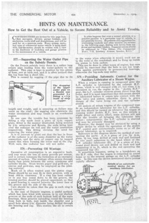
577.—Supporting the Water Outlet Pipe on the Subsidy Dennis.
On the Dennis subsidy lorry there is a rather long return pipe leading from the water-jackets to the radiator, This pipe is kept in position by two pieces of hose, one at each end, and it is often noticed that the top hose has a short life.
This is caused by sagging cf the pipe due to its length and weight, and is annoying as failure may occur on the road ; the sagging also obstructs the water circulation and may result in an overheated engine.
In one case the trouble has been overcome by
fitting a clip made from a piece of copper ailate, fitted in the manner illustrated,_ being secured by 1-in. setscrews-and flynuts, the ends being bent over the radiator tie rod and the water connection respectively. This fitting obviates the need for removing the water pipe.
It is of interest to point out that the bar in front of the radiator is of the same diameter as the water connection, and the strip of copper can be tapped round this when forming the lower end of the clip. With care, the radiator bar will not suffer.
578.—Preventing Oil Wastage.
Excessive oil consumption is an expensive fault, and may mean the loss of many pounds per annum, and in certain instances the formation of an excessive amount of carbon. The wastage often occurs through faulty face joints between the sump, crankcase and cylinder blocks. Stout brown paper and gold-size, or canvas and gold-size, may be employed as the jointing material
Much oil is often wasted past the piston rings. These should be an easy fit in their grooves, with at least .002-in. clearance. If a riag has been rubbed or in any way eased down to fit the groove, the treated portion should be placed uppermost, so that a good bearing is ensured between the lower face of the groove and the side of the ring.
Care should be taken that the gap in each ring is not excessive.
In the case of Daimler engines, a useful method, which has been tried with success, is to cut shallow grooves at the ends of each bottom half of the main bearings, these grooves extending round the bearing from butt to butt, just inside the chamfer and a small hole about.i-in. diameter being drilled through the bearing and cap, This enables the oil to return
B46
to the sump when otherwise it would work out on to the webs of the crankshaft and be flung up inside the piston to form carbon.
This can be done in other types of engine, but care should be exercised that the hole is not too large. This applies particularly to pressure-fed bearings, otherwise the big-ends may suffer.
579.—Providing Automatic Control for the Auxiliary Lubricator of a Steam Wagon. When a wagon is running in compound gear the L.P. cylinder is lubricated by the exhaust H.P. steam, which is well charged with oil, but when it is necessary to run the engine in the "double H.P." gear, the L.P. cylinder receives steam direct from the boiler, and it is most important that this steam should be lubricated before it comes into contact with the slide valve and piston, otherwise there is grave danger of the valve being cut and the cylinder scored.
All makers ,of steam wagons of the compound type fit an independent lubricator for the L.P. cylinder, and this should be turned on whenever the wagon is running under double H.P., but, ii this entails a slight delay and extra effort, some drivers will not take the trouble of bringing the lubricator into action ; consequently, the L.P. cylinder is starved and may be seriously damaged.
However, the danger may be obviated by using a simple device by which the operation of the double H.P. control gear automatically turns on or off the special lubricator, as is required.
Reference to the diagram shows the method of con
necting the parts. A is a piece of by h-in. plate, ai ins, long, drilled at each end and fastened by two small setscrews to the hand wheel of the L.P. cylinder lubricator (B). C is a piece of 4-in. round steel drawn out and drilled at each end and connecting A to D, which is the rod operating the compound tap (E). It sometimes happens, owing to a breakdown on the H.P. side, that the wagon is compelled to travel home or to the nearest garage on the L.P. cylinder only. In this case the device mentioned above proves equally efficient.