


SOME MISCELLANEOUS IMPROVEMENTS.
Page 26
If you've noticed an error in this article please click here to report it so we can fix it.
A Résumé of Recently Published Patents.
The specifications with which we have to deal this week are of general rather than special interest. Probably the simplest will in time be found to he the must significant, and for that reason we will consider No. 133,864 first. Grease cups have been from time immemorial the stumbling block of the car or lorry driver. The careful and conscientious man attends to them most methodically, and finds trouble in the doing of it. The careless or the more casual, generally leaves them elone, and his trouble is coueequently of later date. One of the most recent methods of dealing with the matter took the form of providing the grease in capsules Which fitted into the elms and which gave their contents as the cup was screwed down. The inventors whose patent we are considering, are of opinion that difficulty has been met with in the case of the capsules in that they axe either too weak to sustain the necessary pressure for expulsion.. .f the . grease, or if made strong eurnIgn Tor that purpose they cannot with sufficient ease be emptied. The idea disclosed in the specie
fication under review certainly appears to be worthy of consideration. The patentees suggest that the grease be packed in cart/loves of , cardboard, -shaped in facsimile of the ordinary and familiar brass caps which they will replace. The cartridge will screw on the body of the grease cup, and owing to the softness of the material employed, it is anticipated thatOthere will be no need to screw the eartiidges internally, they will form thejr own thread as they are'.7escrewed into place. It is further claimed that owing to their light weight these cardboard caps will not be so liable to become lost owing to vibration when en the road. A cheek .spring 'will: not, therefore, be required, and, in addition, further economies in the construction of the cup are indicated, as, for'example, in the lack of the need for so 'Eleep74 body of the cup itself. The cartridges themselves will be inexpensive and will be renewed, not refilled.
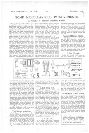
Tivo Rapson Inventions.
F. L. Rapson describes, in specification No. 133,818, an improvement in connection with a previous invention of his own in respect of lifting jacks. The modifications (foe there are several illustrated) refer chiefly to the method of securing the jacks in place on the axles of the ear. In all of them, however, the principal is the same. The ja i ck s mounted on a pin or bearing, and may easily be C44 turned on that bearing. Spring-controlled fastenings secure the jack in either of two limiting positions.. One is the vertical or working position, in which the jack is disposed conveniently for , lifting.the vehicle from the gronncl. The other is with the jack lying horizontally and snugly against the axle. ,'The jack is ' twisted on its pivot and automatically locked in either position by the use of the operating lever as a handle. e
A spherical oscillating type of valve and its operating gear is the subject of No. 133,754, by F. L. Rapson. The two carnS are disposed within the spherical valve chamber above the valve. They are, therefore, easily lubricated and silent in operation. They are designed so that, although one cam moves the valve to one side for opening and closing the exhaust, and the other similarly behaves with regard to the inlet port, the rollers mounted in the valve, on to which the cams bear, are contintiously in contact with the cams. The advantage claimed for this arrangement is that the valve ,is thereby supported againet the upward
thrust due to the compression and the explosion. There are thus three points of support provided ; the two came and the pin or trunnion on which the valve oscillates.
A Self-lifting Jack.
No. 133,917 refers to a self-lifting jack of the type in which both axles of the car are lifted and supported together. A couple of long bars or levers are pivoted at their centres.. A pair of slides near the front end of the levers are formed with stops which receive the front axle, and at the same tune, acting under the memientum of the travelling car, both lift a support for the rear axle, and also by releasing a .spring-held support for the front ends of the levees, allow Ahem to fall forward, lifting the rear portion from the ground and with it the rear end of the car. The car is released and the reverse operation performed by means of a simple lever which lifts the front .end of the apparatus the ear is then reversed and driven off the jacks under its own power, leaving them suitably placed for the reception of the car on its return. The patentee is Hans Pedersen.
A ParallelVice.
In the parallel vice which is described Ia No. 133,898, also by Hans Pedersen, the outer and usually loose. jaw of the vice is oast or forged in one with the
main frame of the vice. The rear or inner jaw is movable and is secured in one of several positions by means of a rack and bolt. Final adjustment of the viee to "suit any object is then achieved by a screw, acting on the tap portion of the -outer jaw. The advantage claimed is the deep gap which is possible between the two jaws.
Vandervell Electric Starter.
A. H. Mid gley and. C. A. Vandervall and Co., Ltd., describe a modification in the design of an electric. starter in No. 133,845. The object is to retard the rotary motion of the starter pinion during the time when it is approaching and engaging the main sour wheel or fly. wheel of the engine. It is accomplished by using the magnetic field produced by the field excitation coils of the electric motor to effect a drag on the pinion.
A Pipe Wrench.
In the pile wrench which is the subject of No. 133,617, by F. TyIdesley, the outer jaw of the wrench is loose and slides in a gap in the other one. " The inner jaw is really a roller, which is supported on a pin held by the body of the wrench. Teeth on the roller engage with a rack on the loose part of the wrench, and the arrangement is such that the loose jaw le automatically tightened on the work as the wrench is turned.
A Four-wheel Driven Tractor.
A four-wheel driven tractor is the sub. ject of No. 133,811. The front axle is bevel driven and pivoted at its centre for movement in the vertical plane only Ackerman-type stub axles Carry the wheels, and the drive is transmitted, as is usual in this form of construction, through universal joints, which are disposed in the centre, of the steering pivots. It is further intended that only one of the axles shall be provided with a differential gear, the wheels of the other one being fitted with free-wheel devices so as to allow one of them to overrun the other.