


An Inertia-assisted Engine Starter
Page 72
If you've noticed an error in this article please click here to report it so we can fix it.
use the energy in a spinning fly wheel to assist the starting of an engine, is the aim of a scheme shown in patent No. 704,395, by V. Silberstein, 14 Phillimore Court, London, W.8. The device can be used in conjunction with an electric starter-motor, and would considerably reduce the maximum effort demanded therefrom.
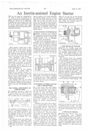
When energy is taken from a spinning flywheel, its effect ceases as soon as the speed of the driven member equals that of the flywheel, although the rotational speed may still be high. To make use of most of this wasted effort is the object of the scheme.
The mechanism used is shown diagrammatically in the drawing. The starter motor (or other turning mechanism) is connected to theinput end (1) and accelerates a flywheel (2). An infinitely variable gear (3) of the toroidal-roller type is interposed in the drive to the pinion (4). As the speed of the flywheel diminishes, the toroidal roller is rocked by. an external control in a clockwise direction and so causes the gear to act as a speed-increaser. This enables much more energy to be extracted from the flywheel.
The toroidal roller can be turned through 180 degrees so that it can act as a clutch to connect the spinning flywheel at the start and disengage it after use.
THE INITIAL ADJUSTMENT OF TORSION BARS IN suspension systems in which the torsion bars. are in the form of a circular rod, the rod can be provided with serrated ends for convenience in the operation of pre-tensioning. In the case of a laminated rectangular bar, however, this method cannot be used. An adjusting device for use in these circumstances is shown in patent No. 703,448, by The Daimler Co., Ltd., Coventry.
The drawing shows the torsion bar (1) in position in a suspension system of the wishbone-link type. The bar is anchored to the frame at the rear and to the link at the front. The adjust a34 ment is made on the vernier principle; the coupling flanges (2) have 20 boltholes for five bolts, whilst those at the other end (3) have 18 holes for six bolts. By removing the bolts and turning the bar through an angle equal to that of one hole-spacing, an advance of two degrees is obtained. This is sufficiently fine for accurately setting the initial tension.
AN OIL-ENGINE CYLINDER-HEAD BETTER turbulence and improved combustion are claimed for a design of cylinder-head shown in patent No. 704,024 (Lanova A.G., 16 Bahnhofstrasse, Zurich, Switzerland).
As seen in the drawing, the piston is provided with a trough-like recess in its crown, and the injector (1) projects into it. On the other side is an air-cell (2) fitted with the usual type of constricted neck. The injector nozzle has its discharge orifices located at one side, so that the fuel is directed towards the air-cell, as indicated by the arrows.
Some of the fuel reaches the cell and is blown back in the form of a flaming jet which sets up a violent turbulence in the piston recess. The patent also covers the use of a pair of air-cells in the same manner.
AN IGNITION CONTROL CUT-OFF FOR CARBURETTERS
IT is well known that some engines
will keep running after the ignition has been switched off. This is due to the fact that some incandescent spot continues to ignite the charge, and engines subject to this phenomenon are often very difficult to stop. A carburetter designed to prevent this is shown in patent No. 702,694, by Solex, 190 Avenue de Neuilly, Neuilly-sur-Seine, France.
Attached to the side of the carburetter is a spring-loaded valve (1) which, in its closed position, interrupts the slow-running tube (2). The valve is provided with an iron core which, when the ignition is switched on, is drawn into a solenoid (3). This action opens the passage, and conversely, when the ignition is cut off, the slow-running passage is immediately blocked, thus stopping the engine by fuel shortage.
To avoid the need for the solenoid to remain energized all the time the engine is running, the valve can be mechanically held open by a finger (4). This can be lifted by a spring, or pulled
• down by an arm (5) on the throttle spindle. If the throttle be opened this finger holds the valve and at the same time breaks the solenoid circuit by opening contact points (6).
A DISC BRAKE BY DUNLOP
DATENT No. 703,860, comes from 1 H. Butler and Dunlop Rubber Co., Ltd., 1 Albany Street, London, N.W.1, and describes improvements in disc brakes. The scheme is intended more for hand brakes employing mechanical operation.
The drawing shows the assembly which is arranged to lie between a pair of hydraulically worked units; in fact it may be considered as a hydraulic unit modified to be worked by a pushrod instead of a fluid. Two piston-like plugs (1 and 2) arc fitted with sealing rings to prevent fluid leakage because they lie in the fluid path from one hydraulic cylinder to the other. The plugs are, however, rendered ineffective by their abntment against circlips (3) and a screwed plug (4).
A push-rod (5)-can press friction-pad 6 on to the disc to effect braking. The push-rod is moved by a lever (7) which is worked by rod or cable. The chief pointof the patent is the use of a wedge (8) which automatically takes up any slack.
A CELLULAR VEHICLE DATENT NO. 705,557 comes from Daimler-Benz A.G., StuttgartUntertfirkheim, Germany, and shows 'a vehicle assembled from three units or "cells," as they are called. Three cells are used, front, middle and rear, and the patent is concerned mainly with the detail fabrication of them from sheet metal.