


A Resume of Recently Published Patent Specifications
Page 46
If you've noticed an error in this article please click here to report it so we can fix it.
A New Method of Mounting Bus Bodies
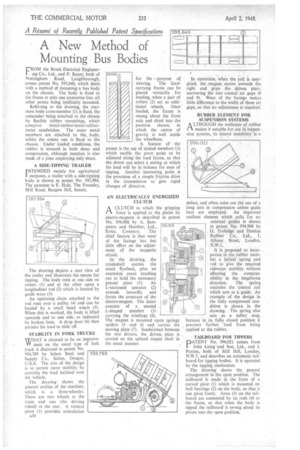
FR" the Brush Electrical Engineermg Co., Ltd., and F. Rayer, both. of Nottingham Road, Loughborough, comes patent No. 595,640, which deals with a method of mounting a bus body on the chassis. The body is fixed to the frame at only one transverse line, all other points being resiliently mounted.
Referring to the drawing, the rearmost body cross-member (1) is fixed, the remainder being attached to the chassis by flexible rubber mountings, which comprise Metal-rubber-metal-rubbermetal sandwiches. The outer metal members are attached to the, body, whilst the centre one is fixed to the chassis. Under loaded conditions, the rubber is stressed in both shear and compression, although mention is also made of a joint employing only shear.
A SIDE-TIPPING TRAILER INTENDED mainly for agricultural 1 purposes, a trailer with a side-tipping body is shown in patent No. 595,984, The patentee is E. -Hole, The Foundry, Mill Road, Burgess Hill, Sussex.
The drawing depicts a rear view of the trailer and illustrates the means for tipping. The body rests at one side on rollers (I) and at the other upon a longitudinal rod (2) which is located by guide ways (3). An operating chain attached to the rod runs over a pulley (4) and can he hauled by a small hand winch (5). When this is worked, the body is lifted upwards and to one side, as indicated by broken lines, A drop door (6) then permits the load to slide off.
STABILITY IN .FORK TRUCKS WHAT is claimed to be an improveVV rnent on the usual type of fork truck is disclosed in patent No. 594,789 by Salem Steel and Supply Co., Salem, Oregon, U.S.A. The aim of the design is to permit more stability by carrying the load inclined over the vehicle.
The drawing shows the general outline of the machine, which is a three-wheeler. There are two wheels at the front and one (the driving wheel) at the rear. A vertical pivot (I) provides articulation a36
for the 4 purpose of steering. The loadcarrying frame can be placed vertically for Loading, when a pair of rollers (2) act as additional wheels. Once loaded, the frame is swung about the front axle and tilted into the position shown, in which the centre of gravity is well inside the wheelbase.
A feature of the patent is the use of slotted members (3) which enable the pivot point to be adjusted along the load frame, so that the driver can select a setting at which his load will be, in balance for ease of tipping. • Another interesting point is the provision of -a simple friction drive in the transmission to' give rapid changes of direction.
AN ELECTRICALLY ENERGIZED CLUTCH
1-1 A CLUTCH in which the gripping force is applied to the plates by electro-magnets is described in patent No. 594,906 by A. Sam"
pietro and Humber, Ltd.,, Stoke, Coventry. The chief feature is that wear of the facings has but little effect on the adjustment of the magnetic circuit.
In the drawing, the• crankshaft carries the usual flywheel, plus an extension cover reaching out to hold the stationary presser plate (1). An L-sectioned annulus (2) extends inwardly and forms the armature of the electro-magnet. The latter consists of a second L-shaped member (3) carrying the windings (4).
The magnet is mounted upon springy spiders (3 and 6) and carries the moving plate (7). Sandwiched between the two drivers, the driven. plate is carried on the splined output shaft in the usual manner.
In operation, when the coil is energized, the • magnet maims towards the right and grips thedriven plate, narrowing the two conical air gaps (8 and 9). Wear of the facings makes little difference to the width of these air gaps, so that no adjustment is required, RUBBER ELEMENT FOR SUSPENSION SYSTEMS A LTHOUGH the resilience of rubber /-1 makes it suitable for use in suspension systems, its lateral instability is a
defect, and often rules out the use of a long unit in compression unless guide bars are employed. An improved resilient element which calls for no
external guides is shown in patent No. 594,908 by 0. Trobidge and Dunlop Rubber Co., Ltd„ 1, Albany Street, London, N.W.I.
It is proposed ta incor-. porate in the rubber member a helical spring and rod to give the required sideways stability without affecting the compressibility in the lengthwise direction: The spring encircles the central rod which acts as a guide. An example of the design in the fully compressed condition is shown in the drawing. The spring also acts as a safety stop, because in its fully closed position it . prevents further load from being applied to the'rubber.
TAILBOARD FOR TIPPERS PNo. 396,021 comes from
John Ling and Son, Ltd., and J. Paxton; both of Mill Hill, London, N.W.7, and describes an automatic tailboard for tipping bodies. It is operated by the tipping mechanism.
The drawing shows the general arrangement in the open position. The tailboard is made in the form of a curved plate (1) which is mounted on . ball bearings (2) on the body, so that it can pivot freely. Arms (3) on the -tailboard are connected by tie rods (4) to the frame, so that when the body is tipped the tailboard is swung about its pivots into the open position.