Independent Suspension, Smooth Acceleration and Battery Accessibility are Featlires of an Advanced Design of Ba ttery
Page 32

Page 33

Page 34

If you've noticed an error in this article please click here to report it so we can fix it.
electric Vehicle
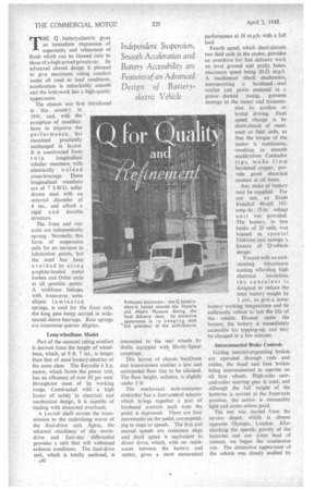
THE Q battery-electric gives an immediate impression of superiority and refinement of finish which can be likened only to those of a high-priced private car. Its advanced chassis design is planned to give maximum riding comfort under all road or load conditions. acceleration is remarkably smooth and the bodywork has a high-quality appearance.
The chassis • was first introduced in this country in 1941, and, with the exception of modifications to improve the performance, has remained practically unchanged in layout. It is constructed from twin longitudinal tubular members with electrically welded cross-bracings. These longitudinal members are of 7 S.W.G. soliddrawn steel with an external diameter of 4 ins., and afford a rigid a n d durable structure.
The front and rear axles are independently sprung. Normally, this form Of suspension calls for an increase in lubrication points, but the need has . been avoided by using graphite-loaded metal bushes and ()Hite units at all possible points. A wishbone linkage, with transverse semielliptic laminated springs, is used for the front axle, the king pins being carried in widespaced sleeve bearings. Rear springs are transverse quarter elliptics.
Long-wheelbase Model Part of the unusual riding comfort is derived from the length of wheelbase, which, at 9 ft. 7 ins., is longer than that of most battery-electrics of the same class. The Reyrolle 6 h.p. motor, which forms the power unit, has an efficiency of over 85 per cent. throughout most of its working range. • Constructed with a high factor of safety in electrical and mechanical design, it is capable of dealing with abnormal overloads.
A Layrub shaft carries the transmission to the underslung worm of the final-drive unit. Again, the inherent sturdiness of the wormdrive and four-star differential provides a unit that will withstand arduous conditions. The final-drive unit, which is totally enclosed, is A30
connected to the rear. wheels by shafts equipped with Hardy-Spicer couplings.
This layout of chassis backbone and transmission enables a low and unimpeded floor line to be attained. The floor height, unladen, is slightly under 2 ft
The mechan ica cam-con tacto r controller has a foot-control selector which brings together a pair of hardened contacts each time the pedal is depressed. There are four movements on the pedal, corresponding to steps or speeds. The first and second speeds are resistance steps and third speed is equivalent to direct drive, which, with no resistances between the battery and motor, gives a most economical performance at 16 m.p.h. with a full load.
Fourth .speed, which short-circuits two field coils in the motor, provides an overdrive for fast delivery work on level ground and partly laden, maximum speed being 20-21 m.p.h. A mechanical check mechanism, incorporating a hardened steel ratchet and pawls enclosed in a
grease packed casing, prevents damage to the motor and transmission by careless or brutal driving. Each speed change is by
short-circuit of resistance or field coils, so that the torque of the motor is continuous, -resulting in smooth acceleration. Contactor tips, made from hardened copper, provide good electrical contact at all times.
Any make of battery may be supplied. For our test, an Exide Ironclad 40-cell 192amp.-hr. (5-hr. rating) Unit was provided.
The battery, in two banks of 20 cells, was housed in special Elektron cast casings, a feature of 0-vehicle design.
Treated with an acid resisting bituminous coating affording high electrical insulation, the container is designed to reduce the total battery weight by 1 cwt., to give a lower battery working temperature and be sufficiently robust to last the life of the • vehicle. Housed under the bonnet, the battery is immediately accessible for topping-up, and may be changed in a few minutes.
Interconnected Brake Controls Girling , internal-expanding brakes are operated through rods and cables, the hand and foot brakes being interconnected to operate on all four . wheels. High-ratio camand-roller steering gear is used, and although the full weight of the batteries is carried at the front-axle position, the action is reasonably tight and caster.action good.
The test was started from the service depot; which is almost opposite Olympia, London. After checking the specific gravity of the batteries and our i-ton load of cement, we began the continuous run. The distinctive appearance of the vehicle was closely studied by several van drivers, who were obviously surprised at our rapid acceleration.
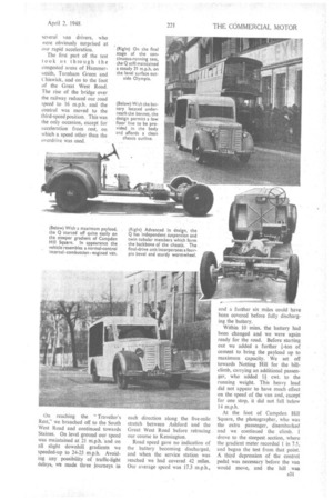
The first part of the test took us through the congested areas of Hammersmith, Turnham Green and Chiswick, and on to the foot of the Great West Road. The rise of the bridge over the railway reduced our road speed to 16 m.p.h. and the control was moved to the third-speed position. This was the only occasion, except for acceleration from rest, on which a speed other than the overdrive was used.
On reaching the "Traveller's Rest," we branched off to the South West Road and continued towards Staines. On level ground our speed was maintained at 21 m.p.h. and on all slight downhill gradients we speeded-up to 24-25 m.p.h. Avoiding any possibility of traffic-light delays, we made three journeys in each direction along the five-mile stretch between Ashford and the Great West Road before retracing our course to Kensington.
Road speed gave no indication of the battery becoming discharged, and when the service station was reached we had covered 42 miles. Our average speed was 17.3 m.p.h., and a further six miles could have been covered before fully discharging the battery.
Within 10 mins. the battery had been changed and we were again ready for the road. Before starting out we added a further i-ton of• cement to bring the payload up to maximum capacity. We set off towards Notting Hill for the hillclimb, carrying an additional passenger, who added 1 cwt. to the running weight. This heavy load did not appear to have much effect on the speed of the van and, except for one stop, it did not fall below 14 m.p.h.
At the foot of Campden Hill Square, the photographer, who was the extra passenger, disembarked and we continued the climb. I drove to the steepest section, where the gradient meter recorded 1 in 7.5, and began the test from that point. A third depression of the control pedal was necessary before the van would move, and the hill . was climbed at a minimum speed of 6 m.p.h, with a battery discharge of 300 amps. at 66 volts.
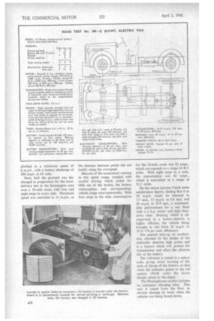
Next, half the payload was discharged in preparation for the localdelivery test in the Kensington area over a 10-mile route, with four and eight stops to every mile. Maximum speed was restricted to 16 m.p.h., as the distance between points did not justify using the ovcrspeed.
Because of the economical running in this speed range, coupled with careful driving which called for little use of the brakes, the battery consumption and correspondingvehicle range were noteworthy. With four stops to the mile, consumption
for the 10-mile route was 42 amps., which corresponds to a range of 40.1 miles. With eight stops to a mile, the consumption was 42 amps., which is equivalent to a range of 31.3 miles.
On the return journey •! to'ok some acceleration figures, finding that 0 to 10 m.p.h. could be attained in 3.7 secs., 15 m.p.h. in 8.8 secs. and 20 m.p.h. in 29.9 secs., a commendable performance for a van fitted with a 6 h.p. motor and high finaldrive ratio. Braking, which is allimportant in a battery-electric, is. highly efficient; the vehicle being brought to rest from 20 m.p.h. in 18 ft. (74 per cent. efficiency).
The smooth take-up on acceleration afforded by the design of the controller deserves high praise and is a feature which will protect the transmission and affect the ultimate life of the battery.
The voltmeter is scaled in a colour code, giving visual warning of the state of charge of the battery, so that when the indicator points to the red section (50-60 volts) the driver should return to the depot.
The Westinghouse rectifier includes an automatic charging relay. This unit is raised from the floor to obviate damage by water when the vehicles are being hosed down.


