


Latest Daimler Trolleybus Chassis
Page 31
If you've noticed an error in this article please click here to report it so we can fix it.
THE first of a series of eight Dairrder three-axle trolleybus chassis, which are being supplied to Rotherham Corporation, was inspected last week by Press representatives at the Coventry works of Transport Vehicles (Daimler), Ltd. it is claimed that the improved materials and manufacturing methods incorporated in the chassis will give greater satisfaction in use and lower operating costs.
Alternative electrical equipment can be installed, Chassis fitted with English Electric equipment will be designated the CTE.-type, those With Metropolitan Vickers gear the CTM, type, and Crompton. Parkinson electrically equipped vehicles the CTC. type. • • ; The, driver's cab has a plywood floor and is mounted on a sub-frame structure bolted directly to the fore end of the chassis frame. Master controller gear is located to the off side of the platform: The operating levers project through the bottom of the casing and are., connected to the pedals. The driver's Seat is positioned on tcip of the casing Of the controller, and both the ca-sirig and •'seat can be easily 'removed as separate unith to gain access to the working parts.
Provision is made for mounting the
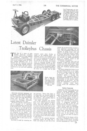
contactor panel either flexibly or rigidly on the bulkhead panel. An inspection panel in the bulkhead gives access to the connections at the rear of the contactor equipment. Located on the off side of the frame, the traction motor is connected through a short single-piece propeller shaft to the foremost wormshaft of the rear-axle bogie. The layout of the transmission shaft is such that when the vehicle is half laden the drive is a straight line in plan
and elevation. When fully laden or travelling light, the universal joints do not deflect more than 2-21 degrees in each direction. The propeller shaft is of the Layrub 100 series.
The bogie comprises two driving axles of the underslnng-worm 'pattern, fitted with worm gearing at .81-in. centres and fully floating axle shafts. To ensure that each axle takes its own proportion of driving torque and to promote tyre life, the foremost axle is fitted with' a third differential unit. With. the heavy stresses .set up by highacceleration and braking, special attention has been paid to the driving shafts, which are machined from steel drop forgings
Of high quality. ''• • Fitted with the patented Kirkstiell suspension system, the bogie has a single road spring on each side of the chassis, the top leaves being extended to form additional. anchorages for the axles. This arrangement eliminates the necessity of fitting torque rods and effects a considerable saving in weight, all driving and torque reactions being taken through the springs. The springs are mounted on needle-roller-bearing pivots in trunnions bolted to the chassis-frame side-members.
A Daimler standard front axle of H-section is fitted and equipped with swivels made from 45-ton steel. These swivels are mounted on king-pins provided with hardened spherical thrust washers.
The power-assisted foot brakes on all six road wheels :operate in two states. Rheostatic braking retards the vehicle to 14 m.p.h., after which the compressed-air system is brought into operation. The maximum effort is governed automatically by the electrical characteristics of the traction motor, independently of the driver. By this means the transmission is relieved of excessive stressing, whilst heavy currents across the commutator are avoided.
Safety Controls
Application of the brake pedal sets up rheostatic braking immediately, irrespective of the power pedal position. Power cannot be restored until both pedals are returned to the off position.
The compressor motor, mounted on the chassis frame adjacent to the compressor, is of English Electric manufacture and is of 1.19 h.p. continuous rating. A compressor governor is located on the floor of the cab and operates between 75-110-lb. pressure.
Brake drums, which are detachable without removing the hubs, are made from cast iron and fitted with antisqueak bands. Internal diameter of the drums is 161 ins, and the total brake friction area of the facings is 913
sq. ins. Facings thick are fitted to all the shoes.
Overall length of the chassis is 30 ft. and it has a wheelbase of 18 ft. 71 ins. Total weight of ./the chassis, including electrical equipment, is .5 tons 9 cwt.