


AN AUTOMATICALLY VARIABLE FRICTION GEAR.
Page 70
If you've noticed an error in this article please click here to report it so we can fix it.
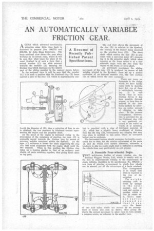
AGEAR which attracted considerable attention some little time back is described in patents Nos. 306,752 and 306,753, by John Hogg Robertson. The large sectional view shows the gear when working on its lowest ratio, where it will he seen that what takes the place of the usual flywheel is of such a form that a second member (C) can slide outward towards the member (E) carrying the friction ring which impinges on the conical part of the sliding member in the manner shown below.
In the sectional view it will be seen that the member (A) is in such a position that the frictional ring (E) bears against a part of the cone (C) which is approximately one fourth the diameter of (B), thus a reduction of four to one is obtained, the two members in frictional contact representing the engine and the propeller shaft.
As the speed of the engine is increased owing to the overcoming of the resistance of starting, the cone (C) is gradually moved towards the friction ring by means of governor weights contained within the flywheel. As the ,cone (C) advances it draws the shaft supporting the ring .(B) into axial alignment with the engine shaft until the
two coincide. When in this position the friction ring takes up a hearing similar to that of an ordinary cone clutch, all parts revolving together, thus giving direct drive on top gear, The end view shows the movement ol the disc (B) in relation to the flywheel, the bearing of the former being mounted
on the pivoting lever (E). The short shaft which carries the disc (33) is provided with a universal joint (V) connecting it to the propeller shaft, which when running on the lower ratios is at a considerable angle with the line from the engine to the worm or bevel shaft.
As previously mentioned, the sliding movement of the cone (C) is produced by means of bob weights pivoted to the flywheel ; these set up a partial revolution of an internal member (G), the cam surface (I) of which forces the cone outwards.
There are many refinements in the design which we have hardly space fully to describe here; but one of them is particularly interesting. It is well known that in most friction drives it has been possible, through misuse, to form flats or hollows in the frictional surface by allowing an undue amount of slipping to take place. In the present arraugement, however, this is provided for, as the frictional ring (B) is not positive] attached to the wheel on which it is mounted, but is provided with a ring of frictional material at • (A), which has a slightly lower co-efficient of friction than has the ring (B), consequently any slipping that may take place is confined to this point, where no unwanted hollow can be produced.
The last-named feature should overcome the trouble experienced due to flats, but the relative adjustment of the parts (A and B) would need careful attention, otherwise a tendency to slip too easily might lead to difficulty in starting the vehicle from rest, particularly on soft ground.
A Steerable Four-wheeled Bogie.
THAT well-known builder of steam vehicles, etc., the Sentinel Waggon Works, Ltd., which is usually well to the fore in iinprovernents relating to the construction of steam vehicles, describes in its specification No. 306,733 a new form of steering arrangement in which four wheels can be steered, yet all the advantages of a bogie retained.
• The arrangement is so simple that little is required in the way of description.
The weightcarrying axle is borne by springs in the usual manner, and at each end carries a member which is free to rotate on it. This member curves around so that it can carry the heads of two stub axles, which are stee .ed by an arrangement of levers and rods as shown, thus giving the wheels the correct movement to allow them to turn around a cm:Union:centre, as indicated in the smaller view.