A NOVEL PROPELLER-SHAFT-COUPLING DEVICE.
Page 49

If you've noticed an error in this article please click here to report it so we can fix it.
Details of the Patent Specification Concerning the Salerni Invention for Facilitating Gear Changing.
MUCH has been written lately regarding the Salerni special form of dog-clutch coupling, which is claimed greatly to facilitate gear changing and to possess some remarkable characteristics. The patent number is 306,636, and it is taken out by Piero Mariano Salerni, a subject Of the King of Italy. It is a very long specification, having some 29 claims, although the device, as described, is a comparatively simple affair. The abject of the invention appears to be to provide a dog clutch of ordinary construction which can be actuated by means of a fork, so far as disengagement is concerned, and by a spring to cause engagement. The coupling is described as being situated behind an ordinary gearbox, and is provided so that a total disengagement of the gearbox shaft from the propeller shaft can be effected while coasting or changing gear.
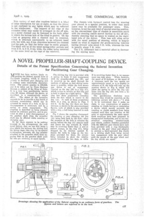
So far there appears to be nothing Unusual -in the arrangement, the only novel feature that we can find being a ring which lies betkveen the driving and the driven dogs; this ring, by its special construction,prevents the dog member attached to the propeller shaft from engaging that on the gearbox shaft until the two are revolving at equal speeds. The driving dog (A) is provided with a spring to force it into engagement with the propeller-shaft dog (B), and is mounted on its shaft through the medium of splines, so that sliding movement is possible, whilst the fork shown can throw it out of engagement. Carried on the dog (B) is a ring (C), which is free to revolve on that dog and is held in place by a light spring. This ring has three projections extending from the face which is nearer to the dog (A). In each of these projections there is a step, as shown in Figs. 3 and 4. In the dog (A) there are three recesses, as shown in the aforementioned figures, each of which is also provided with a step, a ball being inserted in each recess.
Fig. 1 shows the coupling disengaged for coasting or gear changing, the dog (A) being held back by the fork ; when the pressure of the fork is released the spring behind the dog (A) asserts itself and forces the dog towards B, which may be revolving faster than A and so -cannot engage, as the ring (C), being dragged by its friction against B, causes the balls to lodge on the two steps provided for them, the arrows being intended to show the relative speeds between the two dogs, so while B is revolving faster than A, no engagement can take place. When, however, the speed of B declines, or the speed of A increases until the two speeds are approximately equal, or A is slightly in advance of B, the balls will take up the position shown in Fig. 4, which will allow the spring to drive the dog (A) home into the dog (B) and form a bidirectional drive.
The specification disclaims more features than would be expected, as the
following extract will show I wish it to be understood that I make no claim to any construction of positive coupling or clutch having or comprising a device which merely prevents the coupling or clutch members from being engaged until they are rotating at the same or approximately the same speed. Such couplings have been proposed in change-speed mechanism, and in one construction comprising constant-mesh gear wheels, positive clutches associated with the different gear wheels have each been provided with a ring frictionally carried on the gear wheel and adapted to prevent a hand-operated dog clutch on a driving shaft from being moved into engagement with the gear wheel until the speeds of the gear wheel and the dog clutch are equal."


