


Patents Completed.
Page 22
If you've noticed an error in this article please click here to report it so we can fix it.
A Decompressor for a Sleeve-valve Engine. Improving the Speedometer Drive.
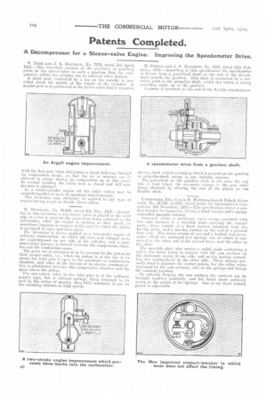
P. BURT AND J. S. MATTHEW, No. 7879, dated 3rd April, 1g13.—This invention consists of the provision of auxi-!iary pasts in the sleeve-valve in such a position that the cornkxession within the cylinder can be relieved when desired.
A small port, controlled by a tap on the outside, is provided about the middle of the length of the cylinder. A aleailar port is so aositioned in the sleeve-valve that it registers
with the first port when thepiston is about half-way through its compression stroke, so that the air or mixture can In allowed to escape during its compression up to this point. In normal working the relief cock ia closed and full coni. pression is obtained.
In a multi-cylinder engine all the relief valves may be coupled together so as to be operated simultaneously. This invention may obvionsly be applied to any type of engine having single or double sleeve-valves.
E. MEDmoaa, No. 10,668, dated 6th May, 1913.--Accordfog to this invention a non-return valve is placed in the inlet pipe in order to prevent the gases from being returned to the carburetter when the engine is running at slow speed, as sometimes happens in engines of the type in which the piston is arranged to open and close ports.
The invention is shown applied to a two-stroke engine of ordinary construction, in which the inlet and exhaust ports are superimposed on one side of the cylinder, and a communicating passage is formed between the compression chamber aud the combustion space.
The ports are so arianged as to be overrun by the piston in their proper order, i.e., when the piston is at the top of its stroke the inlet port is open to the crankcase or compression chamber, and when at the bottom of its stroke, eunununieation is established between this compression chamber and the space above the piston.
The non-return valve in the inlet pipe is of the ordinary poppet type, but is without springs, being returned to its scat by the action of gravity, thus little resistance is put on the incoming mixture at high speeds. H. PERROT and J. S. MATTHEW, No. 4751, dated 25th February, 1913.—According to this specification the speedometer is driven from a gearwheel fixed on the end of the drivenshaft outside the gearbox, This shaft is connected by a universal )oint, to the propeller shaft, which lies within a casing extending right up to the gearbox. A pinion is mounted on the end of the flexible speedometer driving shaft, within a housing which is scured on the gearbox or propeller-shaft casing in any suitable manner. The gearwheel on the gearbox shaft is the same for any size ef road wheel, the necessary change in the gear ratio being obtained by altering the size of the pinion on the flexible shaft.
UNIONWERK MEA, G.M.b.H. Elektrotechnisch Fahrik Eisenwerk, No. 2,3,739, of 1913, dated under the International Convention. 5th -December, 1912.—This specification shows a contact-breaker for magnetos, having a fixed contact and a springcontrolled movable contact.
Arranged within a stationary cuter casing provided with two earn surfaces is a movable plate earring the contact parts ; these consist of a fixed contact insulated from the moving plate, and a moving contact on the end of a pivoted bent 1,7111. The latter carries at one end a hooked nose-piece, ander which are arranged two springs one of which is eon heel( d to the other end of the curved springs, and the other to the plate.
The movable plate also carries a radial guide containing a roller, the latter being in contact with the cam surfaces on the stationary casing at one side, and on the springs controlling the rocking-lever at the other side. These springs normally tend to separate the contact points, but the roller, when depressed by the cam surfaces, acts on the springs and brings the contacts together.
By suitably shaping the cam surfaces the contacts can be brought together gradually, and the break made suddenly owing to the action of the springs. One of the fixed contact pieces is adjustable.