


Injector Nozzle Testing Unit
Page 74
If you've noticed an error in this article please click here to report it so we can fix it.
A UNIT for testing injector nozzles is 1-11-shown in patent No. 870,828. (A.B. Gotaverken, Box 885, Goteborg 8. Sweden.) Referring to the drawing, the nozzle (I) under test discharges into a transparent box so that the form of the spray can be easily observed. The pressure on the fuel is generated by a, small piston working in a cylinder (2). The piston, which corresponds in size to that of a conventional fuel-pump plunger, is con
TWO-PART COMBUSTION
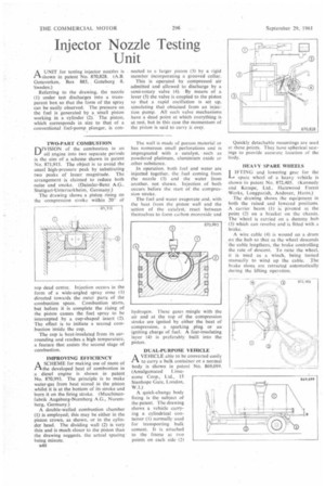
DiVISION of the combustion in an oil engine into two separate periods is the aim of a scheme shown in patent No. 871,915. The object is to avoid the usual high-pressure peak by substituting two peaks of lesser magnitude. The arrangement is claimed to reduce both noise and smoke. (Daimler-Benz A.G.. Stuttgart-Unterturkheim, Germany.)
The drawing shows a piston rising on the compression stroke within 20° of op dead centre. Injection occurs in the form of a wide-angled spray cone (I) directed towards the outer parts of the combustion space. Combustion starts, but before it is complete the rising of the piston causes the fuel spray to be intercepted by a cup-shaped insert (2). The effect is to initiate a second combustion inside the cup.
The cup is heat-insulated from its surrounding and reaches a high temperature, a feature that assists the second stage of combustion.
IMPROVING EFFICIENCY
ASCHEME for making use of more of the developed heat of combustion in a diesel engine is shown in patent No. 870,993. The principle is to make water-gas from heat stored in the piston .whilst it is at the bottom of its stroke and burn it on the firing stroke. (Maschinenfabrik Augsburg-Nurnberg A.G., Nuremberg, Germany.)
A double-walled combustion chamber (I) is employed; this may be either in the piston crown, as shown, or in the cylinder head. The dividing wall (2) is very thin and is much closer to the piston than the drawing suggests, the actual spacing being minute.
a40 nectcd to a larger piston (3) by a rigid member incorporating a grooved collar.
This is operated by compressed air admitted and allowed to discharge by a semi-rotary valve (4). By means of a lever (5) the valve is coupled to the piston so that a rapid oscillation is set up, simulating that obtained from an injection pump. All such valve mechanisms have a dead point at which everything is at rest, but in this case the momentum of the piston is said to carry it over.
The wall is made of porous material or has numerous small perforations and is impregnated with a• catalyst, such as powdered platinum, aluminium oxide or other substance.
In operation, both fuel and water are injected together. the fuel coming from the nozzle (3) and the water from another. not shown. Injection of both occurs before the start of the compression stroke.
The fuel and water evaporate and, with the heat from the piston wall and the action of the catalyst, react between themselves to form carbon monoxide and hydrogen. These gases mingle with the air and at the top of the compression stroke are ignited by either the heat of compression, a sparking plug or an igniting charge of fuel. A feat-insulating layer (4) is preferably built into the piston.
DUAL-PURPOSE VEHICLE
AVEHICLE able to be converted easily to carry a bulk container or a normal body is shown in patent No. 869,099. (Amalgamated Lime
stone Corp., Ltd., 15 Stanhope Gate, London, W.I.) A quick-change body fixing is the subject of the patent. The drawing shows a vehicle carrying a cylindrical container (1) normally used for transporting bulk cement. It is attached to the frame at two points on each side (21 Quickly detachable mountings are used at these points. They have spherical seatings to provide accurate location of the body.
HEAVY SPARE WHEELS
LIFTING and lowering gear for the spare wheel of a heavy vehicle is shown in patent No. 872,405. (Kennedy and Kempe, Ltd., Harewood Forest Works, Longparish, Andover, Hants.)•
The drawing shows the equipment in both the raised and lowered positions. A carrier beam (1) is pivoted at the point (2) on a bracket on the chassis. The 'wheel is carried on a dummy hub (3) which can revolve and is fitted with a brake.
A wire cable (4) is wound on a drum on the hub so that as the wheel descends the cable lengthens, the brake controlling the rate of descent. To raise the wheel. it is used as a winch, being turned manually to wind up the cable. The brake shoes arc retracted automatically during the lifting operation.