


A Resume' of Recently Published Patent Specifications
Page 72
If you've noticed an error in this article please click here to report it so we can fix it.
GEARBOX
IMPROVEMENTS
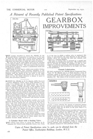
MHE gearbox described in patent No. 355,53% by the General Motors Corporation, of America, is of the type in which the main shaft has, a central portion spigoted at each end into the shafts that protrude from the box ; the right-hand end being that at which the engine is situated. The gears are of the usual sliding kind and are operated by two selector sliding rods, which in the drawing are shown to lie one behind the other. The main point of the invention would, however, appear to concern a synchronous clutch and its means for operation.
This clutch is of the kind in which cones produce friction when brought together, thus operating something in the nature of a baulk ring which prevents the positive dogs from engaging until the speeds of the two .parts of the shaft synchronize. Movements of the selector iods cause the racks shown to free the clutch whenever a change of speed is made, thus preventing clashing.
pATENT No. 355,482, by E. D. Bieretz, 3,208, Hayward Avenue, Baltimore, U-.S.A.; and J. Neal, describes a gear which, it is claimed, may be changed from one ratio to' another without releasing the main clutch. The various gears are always in mesh, and those on the layshaft are of such a width that the gears on the main shaft can move' sideways when required, but will at all times be in mesh.
The left-hand end of the main shaft is that which leads from the engine and into which the driven shaft is spdgoted. The driven shaft is provided with a quick-pitch screw thread, which is interrupted in •places, as shown on the.left, where the direct-drive clutch is situated. This clutch and the bores of the two gears shown are provided with internal threads to tit those on the shaft.
When the gears and the direct-drive member are in the positions shown they are all on the part of the shaft where there is no screw thread and are consequently all free to rotate. The ends of the threads of the shaft and the bores of gears and direct-drive member are visible in the illustration from which it will be seen that, when pressed sideways, the ends of the threads act as dogs, causing engagement, which is free at first, but becomes a positive drive when the member is screwed up against one of the large collars that are firmly fixed to the screwed shaft.
Sleeves attached to the internally screwed members cover the space between them and the collars, into which oil is said to pass, acting as a dash pot to. relieve shock when the members becomes finally screwed up.
A Cylinder Head with a Sealing Valve.
THE cylinder head shown in patent No. 330,710, by E. Adamson, 47, Varick Court, Rockville Center, New York, is of the type in which a sealing valve is employed, this being of approximately the same diameter as the cylinder. Smaller valves are provided for inlet and exhaust, each leading to a separate chamber.
The main or sealing valve is operated by a special cam which causes two openings for each cycle. The smaller valves can be operated by suction or pressure, or may be controlled.by a solenoid co-operating with the ignition system.
The usefulness of this invention is not made very clear in the specification.
Chassis Lubrication.
IN their speeification No. 355,392; Morris Commercial Cars, Ltd., W. W. Hamill and 3.-J, Pratt describe a form of lubricator which is intended for use in connection with a central supply of oil from a pump to all parts such as spring shackles, etc. The object of the invention appears to be to provide a means whereby the amount of lubricant passing to the various parts can be regulated by adjusting the aperture through which the oil flows, at the point where it is introduced to a bearing.
For this purpose a central stem is provided with a screwed end which can be fixed in an ordinary oil hole. This stem is bored partly through, and has a hole at right angles through which • the oil can enter from a pipe and the amrounding socket shown. Around the stem is a spring clip which is provided with a number of holes, varying in diameter, or in some cases with a tapering slot. The stem can be turned around so that a hole of suitable diameter, or a part of the slot of suitable width, is opposite the delivery passage, thus regulating the delivery of the oil to the amount required for each particular bearing.