A NEW Piston-type I N connection with numerons attempts which have
Page 51

If you've noticed an error in this article please click here to report it so we can fix it.
been made in the past to produce a satisfactory fuel pump of the piston type, the problem of providing an adequate seal between the piston and its cylinder has invariably proved one of much difficulty. It is gratifying to learn that a British concern, Amalgamated Carburetters, Ltd., of Perry Barr, Birmingham, appears to have solved the problem in a neat and ingenious manner, as is indicated in the following description of the method of construction and use of the Pump.
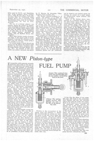
The piston is backed by a coil spring (E) which tends to force it into the cylinder. Connected to the back of the piston by a "lost motion" arrangement is a plunger (B), also provided with a spring which, however, moves the plunger, therefore the piston, in the direction opposite to that imparted by the larger spring, which is somewhat weaker. Operating on the end of the plunger is an eccentric which can be mounted on the camshaft or any other convenient part of the engine. As this eccentric forces the plunger inwards, the piston is relieved of the effect of the small spring and is therefore forced inwards by the large spring. During the next half-revolution of the eccentric the small spring again comes into play and withdraws the piston.
Running circumferentially around the cylinder isa groove (T), and this is connected to the filter chamber (J) beneath it. Any fuel which may escape between the piston and the cylinder must reach this groove, and, as will be explained later, the filter chamber and the groove are maintained at a pressure appreciably below that of the atmosphere, so that the leakage is drawn down into that chamber. Because of this depression it is a fact that small quantities of oil are actually sucked from the engine along the plunger and eventually along the skirt of the piston to the filter, thus showing that there can be no possibility of petrol leaking out.
Turning to the arrangement of the valves, ports and passages,. it should first be noted that no springs are used, the action of the ball valves being due entirely to gravity. The pipe (F) leads from the fuel tank, and the valve (G) is weighted so as to form a definite obstruction to the passage of the fuel. This resistance in itself causes the depression to occur in the filter chamber and those passages which are connected directly with it. After passing through the fine gauze filter, fuel passes up through the suction valve (K) into the pump cylinder and is eventually forced through the outlet valve (L).
It has then the choice of two paths. The pipe (M) leads to the carburetter float chamber aud fuel will naturally pass to that until the needle valve closes. Such of the liquid as is not required by the carburetter passes through the passage (0) to the weighted pressurecontrol valve (P) and thence along the pipe (R) back to the fuel tank. The weight on the valve (P) and the strength of the large spring which operates the piston are so proportioned that the pressure head within the pump never exceeds some 2 lb. per sq. in., and, in fact, remains constant at that figure over a wide range of speeds.
An incidental but important advantage of the separate return pipe to the tank is that, so long as the engine is working, there is a continuous flow of petrol through both the pipes which connect the pump to the tank. Consequently, there is no risk of vaporization taking place within the connecting pipe.
It may be emphasized that this new pump has been exhaustively tested.


