


A NEW COVENTRY CLIMAX ENGINE
Page 46
Page 47
If you've noticed an error in this article please click here to report it so we can fix it.
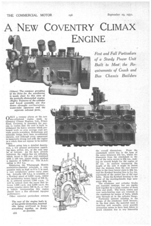
First and Full Particulars of a Sturdy Power Unit Built to Meet the Requirements of Coach and Bus Chassis Builders
riNLY a cursory glance at the new six-cylindered engine made by Coventry Climax Engines, Ltd., Friars Road, Coventry, is necessary for anyone to realize that the unit is built to withstand the heavy stresses which prolonged work on even average road services entails nowadays. Robustness and scientific design have been co-ordinated cleverly, and although every component is immensely strong and stiff, the engine as a whole does not appear to be unduly heavy.
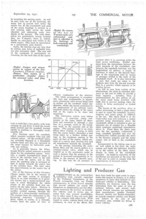
Before going into a detailed description, a few general particulars regarding sizes, power, etc., of the unit may be of interest. As we have already indicated, the engine has six cylinders, which, bored to 120 ram. and combined with a 140 rem. piston stroke, produce a capacity of 6,863.9 c.c. The B.A.C. rating is 38.7 h.p.
Employing the Whatmough Hewitt combustion-chamber principle, a compression ratio as high as 6 to 1 is used, a very satisfactory power curve ensuing. Actually 140 b.h.p. is available at a flywheel speed of 2,550 r.p.m., whilst the satisfactory torque figure of 335 lb.-. ft. is achieved around 1,500 r.p.m. It will be noticed from the curve that between 1,000 r.p.m. and 2,000 r.p.m. the torque remains above 225 lb.-ft., so that a vehicle incorporating this engine shoal(' have a fine all-round top-gear performance.
Other essential particulars concern the overall .dimensions. From the
crankshaft centre line to the base of the sump measures 10/ ins., whilst the dimension from the crankshaft to the top of the valve covers is 251 ins., making an overall height for the engine of 36 ins. In matters concerning the length of the unit it might be stated that the distance from the rear bearer bolts to the front bearer plate is 38k ins. and the flywheel housing face is 3Y6 rearwards of the centre line of the rear bolts. From the flywheel housing to the front of the starting-handle dogs measures 4611ins.
The crankcase and cylinder blocks are separate castings, but are rigidly held together by a large number of stout bolts and studs. The front, centre and rear main-bearing caps are retained in the crankcase by means of bolts, which pass through on to the cylinder flange.
Particular interest attaches to the design of the crankcase itself because,.. in the first place, the material used is cast-iron and, secondly, every possible precaution seems to have been taken to avoid vibration due to any insecurity
in mounting the moving parts. As will be seen from one of the drawings, the sump line i carried well below the centre line of the crankshaft and each of the seven bearings is carried in a web running right across the crank chamber and embracing quite twothirds of the journal. The webs themselves are particularly strong, because they are T-shaped ; there is, indeed, hardly an open-faced, web visible in the whole engine. This must be appreciated as -a particularly good feature.
Again, the bearing caps are very deep in section, and, being of malleable iron, are also extremely rigid. The rear end of the crankcase is particularly interesting, for the back face of the engine body is built like a box girder, with webs running up and down to hold the crankshaft journal and the camshaft journal rigidly in position—a thoroughly workmanlike job.
Five bearings carry, the camshaft, which operates overhead inlet and side • exhaust valves. All the overhead valves are vertically disposed in a detachable cylinder head and they are operated in the usual manner by ball-ended pushrods and rockers.
As is generally known, the Whatmough Hewitt patent concerns a special shape for the combustion spaces. Actually, a roughly hemispherical shape is given to the cylinder head on the side remote from the piston, and in this space the sparking plug is arranged so that it points towards the centre line of the cylinder bore. The inlet valve lies approximately on the centre line of the piston.
One of the features of this Coventry Climax engine lies in the manner in which the inlet system is arranged. There is no inlet manifold as is generally known, but a square-sectioned passage is cored throughout the whole length of the cylinder head and embraces all the inlet valves. Mixture is fed into the centre of this passage from another vertical passage, through the medium of a down-draught carburetter. The passage from the carburetter to the horizontal induction "manifold" is short, which, of course, is a deTsirable feature front the point of view of efficient combustion of the. mixture.
The whole arrangement is exceptionally neat and workmanlike in appearance, aluminium valve covers being used to enclose all the overhead rocker mechanism, whilst the layout permitted by the employment of an.„ external water manifold allows the design of the upper half of the engine to be clean and accessible.
The lubrication system next claims attention. A gear-type pump submerged in the sump draws oil therefrom and transmits it, through a pipe line, to a passage, cored in the crankcase itself on the opposite side of the engine. This passage leads to an AutoKlean filter (which, of course, is built into the engine body), thereafter a lead being taken by a further drilled passage in the crankcase casting to the main oil duct of the engine, which consists of a cast-in pipe running fore and aft immediately beneath the camshaft.
In the passage connecting the AutoKlean filter and the cast-in gallery is a pressure-release valve, which can be coupled up to the accelerator pedal in such a manner that the pressure in the system is increased automatically in relation to the amount of throttle opening. In this way the oil pressure is greatest when it is operating under the most severe conditions. Drilled passages form the connections between the main journals of the crankshaft, also between the camshaft bearings, and the longitudinal oil gallery • a supply of lubricant is taken to the big-end bearings of the connecting rods by means of passages drilled in the webs of the crankshaft itself. It is also interesting to note that leads are taken to the gudgeon pins from the big-end journals. This is a practice which appears to be gaining favour.
As will be seen from certain of the illustrations, the saran is extended sideways at the rear in order to provide a large capacity. Actually, there is accommodation for five gallons of oil, the sump itself being provided with baffle fins to prevent surging when the vehicle is being accelerated or braked heavily.
The layout of the auxiliary drive is rather interesting, in that a single chain is used to rotate the camshaft, dynamo, magneto and water pump, in adaition to the fan. The chain itself is of the triple-roller type and embraces a jockey sprocket lying immediately above the crankshaft, which is included to give an adequate arc of contact for a Renolds chain tensioner positioned immediately above it. From there the chain runs over the fan sprocket, underneath a large camshaft sprocket and over the auxiliary line (which provides the drive to the dynamo, magneto and the water pump) and so back to the crankshaft again.
Incorporated in the timing case is an oil well which is fed from the main system and leads the lubricant directlyon to the rollers of the chain immediately in front of the crankshaft sprocket. As might be expected, all the auxiliaries are mounted on the near side of the unit in order to comply with the requirements of forward control.