


LATHE HINTS FOR MECHANICS.
Page 29
If you've noticed an error in this article please click here to report it so we can fix it.
Suggestions by Some of Our Drivers and Mechanic Readers for Use in the Workshop.
TED milling of bevelled gears on a lathe is not such a difficult job as it would appear ; in this connection, the suggestion of "W.A.S.W.," of
Tiverton, is a practical one, for which this week's prize of 15s. is awarded.
A stout angle r Ile, cut away at one corner, is fixed to the lathe slide rest and the plate cut out to accommodate the . two yes-blocks which act as a mountini, for the spindle of the bevelwheel blank. One of the bolts passes through an ordinary hole and the other through a slot, in order to obtain angular adjustment for the blank. At right angles to the length og the outer vee-block an index line is scribed, which will register with the indices marked on the gear blank. A milling cutter is mounted on a spindle which runs between the lathe centres.
After the blank has been turned and bored, its periphery is divided into sections, equal in number to the teeth required, each section being marked by a fine line. This division can be carried out quickly by means Of the gear train before the blank is removed from the lathe chuck.
When the blank has been mounted on the spindle, the next step is to move the roe-blocks in the slot in such a manner that the correct angle is obtained at the base of the teeth when the milling cutter is in operation. The spindle of the blank is rotated until the index line on the outer roe-block and one of the division lines on the blank coincide. The two bolts passing through the veeblocks are tightened and the cutter then set in motion at a fairly low speed. Care should be taken to keep the blank well lubricated with soapy water during the cutting urocess ; the feeding of the blank in towards the cutter is achieved by means of the cross feed. This method can also be used for spur wheels and pinions. A CHEAP tool for finding the correct degree of taper when shafts have to be turned by means of the top rest of a lathe is suggested by "D.D.I.," of Cleckheaton. Take a piece of strip steel 8 ins. long, 1 in. wide, and j in. thick. A fg-in hole is drilled at one end of the strip, and through this a spindle passes. This is made to the following dimensions :—/ in. wide hexagon faces, hexagon head in. diameter ; next to the head the spindle is turned to * in. diameter for a distance of 5-32 in. The next shoulder is 16-4 in. diameter and 11-32 in. wide ; finally, the end is turned dawn and tapped fin. Whitworth for
in.
A pear-shaped piece is then constructed, its dimensions being 11 ins. overall length, / in. maximum width, and * in thick. This has a hole * in. diameter drilled towards the wide end, and is mounted on the 4-in. diameter part of the stud, the bolt being tightened up.
Taking a shaft 2 ins, in diameter, which is tapered to 1-Ai ins, for a distance of 41 ins., turn the 1N-in. part to the length required and measure off 4i ins. The tool above described is next fastened in the tool post and the point of the pear-shaped piece brought into contact with the shaft, touching the 1-11,-in. diameter section. Swivel back the pear-shaped piece and wind the top rest 41 ins., that is, to the top of the taper, and see if the pear-shaped piece touches the shaft when it is turned round so that the point is farthest from the shaft. If the " pear " touches the shaft at the extremities of the portion to be tapered, first with the pointed end and then with the blunt end, the correct setting has been obtained.
TL-RNING eccentric parts is not always easily accomplished, and " P.B.V.," of London, S.W.18, comments upon the method commonly employed in this connection, namely, the insertion of a packing piece between one of the jaws of the chuck and the work, of such a size that it compensates for the eccentricity. This method, he states, is satisfactory when a fourjaw chuck be used, but when a threejaw self-centring type is employed conditions are altered, as all three jaws recede together and the packing must be thicker than the required throw, which can only be determined by experiment or difficult calculations.
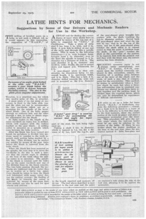
TN order to set up a lathe for tap6r
work, "H.A.B.," of Rotherham, suggests the following procedure :—Assuming a bush is to be bored to a taper of 1 in 5, the difficulty is to find this angle. In the first instance, draw the correct section of the work on paper and place a transparent protractor over the drawing. This procedure will give the carreet angle which the tool-rest holder must be set over in relation to the centres of the lathe. If there be any doubts about the degree markings on the base of the tool post, place the protractor against th, lathe face-plate an(
an engineer's ride along the side of the tool rest, allowing it to lie against the protractor.