 1
1 2
2 3
3 4
4 5
5 6
6 7
7 8
8 9
9 10
10 11
11 12
12 13
13 14
14 15
15 16
16 17
17 18
18 19
19 20
20 21
21 22
22 23
23 24
24 25
25 26
26 27
27 28
28 29
29 30
30 31
31 32
32 33
33 34
34 35
35 36
36 37
37 38
38 39
39 40
40 41
41 42
42 43
43 44
44 45
45 46
46 47
47 48
48 49
49 50
50 51
51 52
52 53
53 54
54 55
55 56
56 57
57 58
58 59
59 60
60 61
61 62
62 63
63 64
64 65
65 66
66 67
67 68
68 69
69 70
70 71
71 72
72 73
73 74
74 75
75 76
76 77
77 78
78 79
79 80
80 81
81 82
82 83
83 84
84 85
85 86
86 87
87 88
88 89
89 90
90 91
91 92
92 93
93 94
94 95
95 96
96 97
97 98
98 99
99 100
100 101
101 102
102 103
103 104
104 105
105 106
106 107
107 108
108 109
109 110
110 111
111 112
112 113
113 114
114 115
115 116
116 117
117 118
118 119
119 120
120 121
121 122
122 123
123 124
124 125
125 126
126 127
127 128
128 129
129 130
130 131
131 132
132 133
133 134
134 135
135 136
136 137
137 138
138 139
139 140
140 141
141 142
142 143
143 144
144 145
145 146
146 147
147 148
148 149
149 150
150 151
151 152
152 153
153 154
154 155
155 156
156 157
157 158
158 159
159 160
160 161
161 162
162 163
163 164
164 165
165 166
166 167
167 168
168 169
169 170
170 171
171 172
172 173
173 174
174 175
175 176
176 177
177 178
178 179
179 180
180 181
181 182
182 183
183 184
184 185
185 186
186 187
187 188
188 SCAMMELL Builds a FOUR-WHEELED LORRY
Page 109
Page 110
If you've noticed an error in this article please click here to report it so we can fix it.
A New Two-axled Machine Incorporating the Well-known 80 b.h.p. Engine T" stand of Scammell Lorries, Ltd., of Watford,. Aliddlesex, at the Commercial Motor Transport Exhibition will present an impressive spectacle. and an entirely new model in the form of a four-wheeled lorry will be seen beside the larger and familiar Scammell six-wheelers and eight-wheelers.
The articulated multi-wheelers, as well as the rigid six-wheeler (which was described in this journal in June, 1927) remain virtually unchanged, although it should be mentioned that — the eight-wheeler now has a trailer-unit frame Constructed with main members 14 ins, in depth. We might also remark that the company has gone to great pains in experinaeats to obtain a calibration for the automatic-advance coupling of the Simms magneto to suit the Scammall engine, and the result has justified the trouble taken.
The rigid six-wheeler, although, perhaps, not seen on British roads in large numbers, is being sold very successfully abroad, especially for service in; oil fields where roads are practically nonexistent.
Dealing now with the new four. wheeler; the object in designing this machine has been to secure fast and economical •road transport for loads of about six tons. To this end the standard Scammell four-cylindered, overhead-valve engine of 5-in bore and 54-in. sfroke has been utilized. This_ engine develops 80 b.h.p. and, in conjunction with a four-speed gearbox, enables the full load to be taken up all ordinary hills on top gear. Ex tended road tests have shown, that with a consumption at the rate of 8 m.p.g. of feel an average speed of 23 m,p.h. is maintained with ease, whilst with a trailer carrying a further load of six tons an average of 20 m.p.h. for long distances has been maintained on a fuel consumption of a gallon per 64 miles.
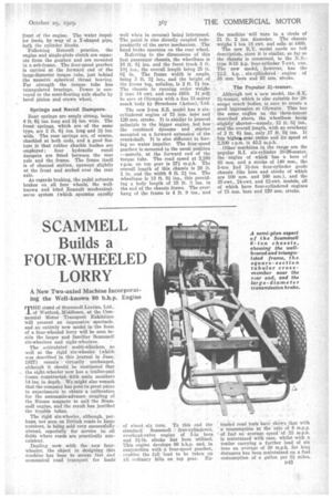
The wheelbase is 17 ft., ,this providirk for a body platform up to 18 ft. In length and an allowance of 4 ft. for the driver's cab. The front track is 6 ft. 2 ins., and the rear track 6 ft.
A. pressed-steel frame of straight channel-sectioned members, 8 ins, deep and having 3-in, flanges, is braced by three tubular cross-members of circular section, a square-sectioned tube (4 ins. by 4 ins.) at the tail end of the rear springs, a similar tube having a section 5 ins, square at the rear of the engine frame and a cored box-section casting which forms the foremost crossmember.
Transmission Details.
The engine and gearbox are carried In a sub-frame between this unusual form of cast cross-member and the square tubular member mentioned above, a trunnion mounting being used at the forward end. The drivelito the gearbox is through an internal-cone clutch, the standard four-speed gearbox with central control being employed. A large tyre-inflation pump is fitted to the gearbox. A two-piece propeller shaft with Hardy-Spicer joints conveys the power to the overheadworm rear axle, this being of the fully, floating type incorporating Timken bearings. The final drive ratio is 7.75 to 1, this being multiplied by the indirect gear ratios of 1.75, 2.7 and 5.09 to 1 (forward) and 6.67 to 1 (reverse).
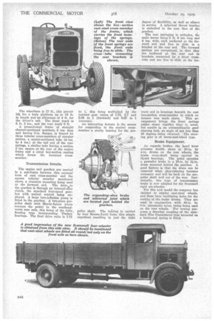
An interesting feature is the means for suspending to the central crossmember a steady bearing for the pro pelIer shaft. The baring is carried by four Simms-jurid links, this simple expedient resulting in just the right degree of flexibility, as well as silence in service. A spherical thrust bearing is embodied in the rear face of the gearbox,
The rear springing is orthodox, the main leaves being .5 ft. 6 ins, long and 4 ins, wide, each anchored at the forward end and free to slide in a bracket at the rear end. The forward springs are exceptional, in that they are anchored at the rear end in' brackets connected by a stout crosstube and are free to slide at the for ward end in housings beneath the cast box-section cross-member to which reference was made above. • This arrangement brings the front springs rather closer together than is usual, but results in an extraordinarily good steering lock, an angle of not less than 45 degrees being obtained. The steering gear is of worm-and-wheel type.
Brake Equipment.
As regards brakes, the hand lever actuates double shoes in 20-in. by 4-in, drums on the rear wheels, the brake cross-shaft being carried in Hyatt bearings. The pedal operates a powerful brake in a 16-in. by 31-in. drum mounted behind the gearbox. A good feature is that the drum can be removed when shoe-refacing becomes necessary and will lie back on the propeller shaft well out of the way. Incidentally, this type of transmission brake is now adopted for the Scammell rigid six-wheeler.
For this new model the company has decided to employ cast-steel wheels, and these have ventilation holes for the cooling of the brake drums. They are used in conjunction with 40-in. by 8-in. pneumatic tyres, twins being used on the rear wheels. For towing purposes a drawbar coupling of the standard War Department type, mounted on a laminated spring is fitted.