 1
1 2
2 3
3 4
4 5
5 6
6 7
7 8
8 9
9 10
10 11
11 12
12 13
13 14
14 15
15 16
16 17
17 18
18 19
19 20
20 21
21 22
22 23
23 24
24 25
25 26
26 27
27 28
28 29
29 30
30 31
31 32
32 33
33 34
34 35
35 36
36 37
37 38
38 39
39 40
40 41
41 42
42 43
43 44
44 45
45 46
46 47
47 48
48 49
49 50
50 51
51 52
52 53
53 54
54 55
55 56
56 57
57 58
58 59
59 60
60 61
61 62
62 63
63 64
64 65
65 66
66 67
67 68
68 69
69 70
70 71
71 72
72 73
73 74
74 75
75 76
76 77
77 78
78 79
79 80
80 81
81 82
82 83
83 84
84 85
85 86
86 87
87 88
88 89
89 90
90 91
91 92
92 93
93 94
94 95
95 96
96 97
97 98
98 99
99 100
100 101
101 102
102 103
103 104
104 105
105 106
106 107
107 108
108 109
109 110
110 111
111 112
112 113
113 114
114 115
115 116
116 117
117 118
118 119
119 120
120 121
121 122
122 123
123 124
124 125
125 126
126 127
127 128
128 129
129 130
130 131
131 132
132 133
133 134
134 135
135 136
136 137
137 138
138 139
139 140
140 141
141 142
142 143
143 144
144 145
145 146
146 147
147 148
148 149
149 150
150 151
151 152
152 153
153 154
154 155
155 156
156 157
157 158
158 159
159 160
160 161
161 162
162 163
163 164
164 165
165 166
166 167
167 168
168 169
169 170
170 171
171 172
172 173
173 174
174 175
175 176
176 177
177 178
178 179
179 180
180 181
181 182
182 183
183 184
184 185
185 186
186 187
187 188
188 An Entirely New
Page 104
Page 105
Page 106
If you've noticed an error in this article please click here to report it so we can fix it.
THORNYCROFT SIX-WHEELER for 10-ton Loads
An Exclusive Description of a New Thornycroft which is Shortly to be put into Production, Embodying Many Novel Features in Construction
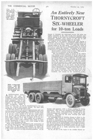
A NOTICEABLE tendency .1.71. during the past few months has been towards the production of larger chassis for goods transport. One of the most striking newcomers to this category is the Thornycroft rigid six-wheeler, which is known as Type JO. It will be manufactured in two patterns, viz., forward and normal control. We here refer specifically to the forward-control type.
• Inthe first instance the general measurements will indicate the proportions of the chassis :—Wheelbases, 14 ft. 6 ins. and 4 ft. 6 ins. ; overall length, 26 ft. 84 ; overall width, 7 ft. 31 ins. ; track (front), 6 ft. 2; ins. ; track (rear), 5 ft. 91. ins. ; ground clearance under front axle, 10 ins.; body space (rear of cab to end of frame), 21 ft. 7k ins. ; frame height -(laden), 3 ft. The weights are as follow :— Front axle, 2 tons 1 cwt. ; driving axles (total on bogie
equally distributed), 4 tons cwt. ; total weight, 6 tons 1-1 cwt. ; body allowance, 25 cwt.
Many novel features are embodied in the construction of the JO-type Thornwroft. The most striking at a first glance is that three of the frame cross-members are above the chassis frame and the fact that they extend to the full width of the vehicle and serve as body-mounting members. As the D38 chassis is intended for main-road service, the axles are rigidly connected to the ends of the four inverted semi elliptic springs of the bogie, no swivelling mechanism being interposed. Another novel feature is the use of selfenergizing internal-expanding brakes for the lxrgie.
A radiator of the familiar Thorny-croft type, having a gilled-tube core, is carried on cup-shaped rubber buffers on the front end of the frame. The header and base tanks are castings bolted to the tube block. A cowled fan, which is driven by a V belt and has an adjustable pulley, is situated immediately behind the radiator. Circulation of the water is effected by an impeller-type pump, which does not impede thermo-syphon cooling if out of action. The pump is driven by an extension of the fan spindle.
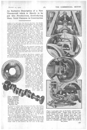
The six-cylindered engine is known as the WB/6type, having a bore and stroke of 4ins. and 5i ins. respectively, giving a piston-swept volume of 474 cubic ins, and an R.A.C. rating of 45.9 h.p. At 1,500 r.p.m. the output is 78 b.h.p., whilst 90 b.h.p. can be developed when the engine is speeded up. The six cylinder barrels are pressed into a single casting which forms the water jacket and carries the valves ; the detachable cylinder heads are in two parts. On the left-hand side of theicylinder block are mounted the side-by-side valves, operated by a camshaft driven from the rear end of the crankshaft. The auxiliaries on the near side, however, are driven from the front end of the camshaft, and consist of the fan-driving ibulley,
dynamo and magneto, with a vernier coupling for timing adjustment. The valves are situated behind detachable oiltight covers. Seven white-metal-lined bearings' carry the nickel-chromium-steel crankshaft in the upper half of the crankcase. The bolts for the main bearings pass right through the crankcase.
An interesting form of vibration damper is fitted to the crankshaft. This consists of a flywheel the centre portion of which is connected to the crankshaft. The rim of this flywheel, however, is frictionally connected to the centre portion 15y means of two spring-loaded, sector-shaped members. Any uneven motion of the crankshaft causes the rim of the flywheel to spin relative to the centre portion, but the springloaded sectors act as a brake, permitting only a slight amount of movement.
On the off side of the engine is the oil-filler funnel, ex
tended to be well above the driver's cab floor ; the flexible (lipstick is also brought up to approximately the same height and is on the same side of the power unit. On the near side are the auxiliaries already named and, in addition, a Solex carburetter fitted with an A.C. air cleaner. There is an asbestos shield above the magneto to deflect any heat from the exhaust-pipe branches, which are in three portions.
Unusual attention is paid to oil filtering. Below the crankshaft there is a gauze tray in the sump to catch the larger carbon particles. Another filter is attached to the submerged pump in the base, and a detachable, rapidly cleanable, three-stage filler is mounted externally on the near side below the centre line of the crankcase. This can be cleaned without loss of oil from the sump. When starting up on a cold day the oil in this filter is automatically by-passed if tile oil be too heavy easily to pass through at the time. Duets in the crankcase are used, the only external pipe being that to the pressure gauge.
Oil passes from the pump to the camshaft bearings and main bearings, the big-ends being lubricated under pressure through the drilled crankshaft. The cylinder walls and pistons are lubricated by spray from the crankshaft bearings, whilst the overflow from the relief valve lubricates the camshaft timing wheels.
Automatic advance is used for the .Sinuns magneto, and the timing can easily be set by removing the starter motor to reveal the marks. on the front of the flywheeL To assist carburation a hot-spot is provided in the induction manifold. The throttle has a hand operated slow-running adjustment below the steering wheel.
The engine and gearbox unit is suspended at three points in the frame. At the front and rear trunnions are employed, one being carried upon a cross-member in front of the crankcase, whilst the -.two. rear points consist of trunnions on brackets at. tacked to the frame. Rubber buffers are used for all three. The rear trunnions are bolted to vertical faces on the crank case so that rapid removal of the power unit is facilitated.. . A dry 'single-plate clutch is . mounted in the flywheeL Six . springs are used to bear upon.
the presser plate which traps be t won itself and
the flywheel a driven disc faced on both sides with friction material. A clutch stop is supplied. On the rear end of the crankcase the gearbox is belted. Four forward speeds are provided and these are controlled by a lever operated by the driver's left hand. The reductions in the gearbox are as follow :—Top gear, direct ; third, 1.56 to 1; second, 2.75 to 1; first, 5.12 to 1; reverse, 7.69 to 1. On the direct ratio the road speed at 1,500 r.p.m. is 16i A two=piece propeller shaft transmits the power, from the gearbox to the forward axle of the bogie. Metallic universal joints are used at all points. The coupling at the forward end of the propeller shaft permits sliding motion and a telescopic shaft is used between the two axles of the bogie.
When normally loaded the transmission line is approximately straight The driving axles coneist of two cast-steel casings with fully floating differential shafts driven by overhead worms, having a reduction ratio of 10i to 1. The worm and differential assemblies can be dismantled without removing the load from the axles.
Four inverted, semi-elliptic springs are pivoted at their centres to brackets rigidly attached to the frame. The springs are also connected rigidly to the driving axles, and they take the driving and braking stresses. The design permits 6 ins, difference in height of the two axleS of the bogie, excessive movement being prevented by rubber buffers above and below the axles. The springs and spring pins are completely enclosed by metallic and fabric covers. The brackets between the springs and chassis frame are built-up to facilitate dismantling. The front springs are secured by the Thornycroft patent relieving plates, which enable the bolding-down bolts to withstand the stresses due to the flexing of the springs. The overall length of the front springs is 4 ft and that of the rear springs is 4 ft. 6 ins.
An H-section front axle is employed ; the swivel arms move on taper-roller bearings and the track rod is behind the axle. Steering is by worm circle is approximately 65 ft.
Pressed-steel channel-section frame members are used, the metal being in. thick, and the maximum depth of the channels 9 ins., with flanges 4i ins, wide. The crossmembers, with the exception of the front one and that which supports the transmission brake, are hollow, of welded-up section, and ate placed above the frame ; they are made of -A-in. steel. A 50-gallon steel tank is carried on the near side of the frame, petrol being drawn from it by a vacuum tank on the front of the dashboard.
Much interest attaches to the brakes. The hand-operated set is of the external-contracting type, working on a wide drum fitted to the rear end of the intermediate propeller shaft. A stout cross-member of the frame takes all the stresses imposed by this brake.
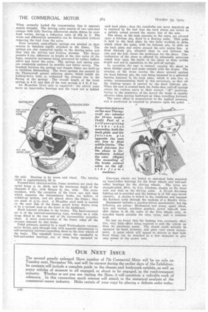
Pedal pressure, assisted by a small Westinghouse vacuumservo device, goes through rods with separate adjustments to self-energizing internal-expanding shoes in the four wheels of the bogie. The camshaft levers rotate the camshafts in ball-and-socket bearings, one of them being mounted on each back plate ;thus the camshafts can move angularly as is required by the fact that the back plates can rotate to a certain extent around the centre line of the axle.
The shoes, at the ends opposite to the cams, are pivoted upon a fulcrum pin, fixed to a floating palm. This palm is held to the back plate by two bolts working in slots. which allow the palm, with its fulcrum pin, to slide on the back plate and rotate around the axle centre line. A fixed fulcrum pin, situated close to and between the cam and the hub, forms the anchorage for the shoes. Centralization of the shoes is effected by adjustable setscrews which bear upon the inside of the shoes at their middle length and act in opposition to the pull-off springs.
In operation the cam is rotated, causing the shoes to move farther apart and make contact with the drums. The rotation of the drum carries the shoes around against the fixed fulcrum pin, the cam being mounted in a spherical bearing fastened to the back plate, which is also free to rotate, accommodating itself to this movement, so that all the braking torque is carried by the fixed fulcrum pin. When the cam is rotated back the brake-shoe pull-off springs return the various parts to their normal " off " positions. Owing to the symmetry of the layout the brake is equally effective when moving backward as when travelling forward.
The servo effect is proportional to the applied pressure, and is graduated as required by pressure upon the pedal.
Disc-type wheels are bolted to cast-steel hubs moanted on taper-roller bearings for the front wheels and ball-and
roller bearings for the driving wheels. The tyres are straight-sided, 40-in. by 8-in. Dunlops, singles on the front -axle and dual on the driving axles. A 12-volt five-lamp lighting set is provided and the battery is of 105 amp.-hours capacity. A starter is bolted to the crankcase and engages the flywheel teeth through the medium of a Bendix drive.
Equipment includes a gearbox-driven speedometer, but the following are extras : Mechanical tyre pump, spare wheel, tyre and carrier, auxiliary gearbox, power take-off, nonskid chains to fit the outer of the twin wheels only, or non-skid bands suitable for twin tyres, and a radiator muff.
On test we found that the braking was extremely effective, very little effort being required to pull the vehicle up from it maximum speed. The clutch could actually be operated by hand pressure, and gave very sweet engagement. A point which will appeal to drivers is that both front wings can be detached in a few moments to give easy access to the power unit.