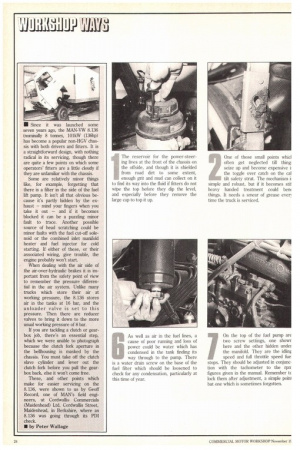
The reservoir for the power-steering lives at the front of
Page 108

Page 109

Page 110

Page 111

If you've noticed an error in this article please click here to report it so we can fix it.
the chassis on the offside, and though it is shielded from road dirt to some extent, enough grit and mud can collect on it to find its way into the fluid if fitters do not wipe the top before they dip the level, and especially before they remove the large cap to top it up. (inc of those small points wind .„.. often get neglected till thing
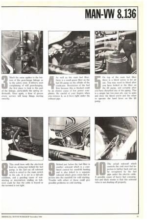
iseize up and become expensive i the toggle over catch on the cal tilt safety strut. The mechanism i simple and robust, but if it becomes stii heavy handed treatment could berm things. It needs a smear of grease ever] time the truck is serviced. 3 Much the same applies to the bottom of the gearchange linkage as to the safety strut. If drivers start complaining of stiff gearchanging, the first place to look is this part of the linkage, particularly the spring underneath. Once again, a dose of grease every service will keep things moving sweetly. 4 As well as the main fuel filter, there is a small gauze filter on the fuel lift pump on the offside of the crankcase. Restriction of the fuel flow because this is blocked could be an elusive cause of low power complaints. Be careful of your fingers when you remove it, as it lives right under the exhaust pipe. 5 On top of the main fuel filter there is a bleed screw to let air out. You may need to bleed after you have looked at the filter on the lift pump, and certainly after you have disturbed any of the piping. This is a simple but two-man job, one to undo and close the bleed screw and the other to operate the hand lever on the lift pump.
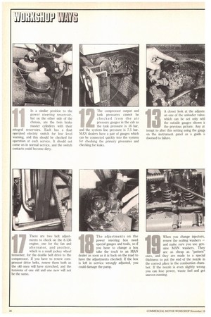
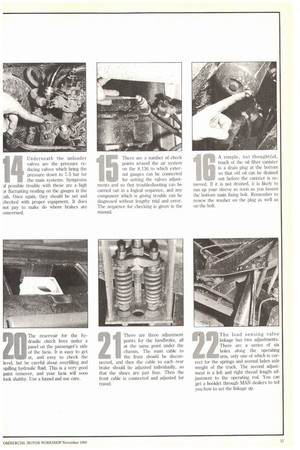
BAs well as air in the fuel lines, a cause of poor running and loss of power could be water which has condensed in the tank finding its way through to the pump. There is a water drain screw on the base of the fuel filter which should be loosened to check for any condensation, particularly at this time of year. 7 On the top of the fuel pump are two screw settings, one showr here and the other hidden under the manifold. They are the idlinf speed and full throttle speed fue stops. They should be adjusted in conjunction with the tachometer to the rprr figures given in the manual. Remember tc lock them after adjustment, a simple poini but one which is sometimes forgotten. 8 This small item with the electrical lead on, sitting just behind the fuel pump, is the fuel cut off solenoid which is wired to the main switch in the cab. It is set in a fail-safe condition, and a puzzling cause of nonstarting or intermittent stalling on tickover could be that the cable is frayed or the terminal is not tight. 9 Behind just below the fuel filter is another solenoid which is a combined control for manifold heating and is also linked to a separate solenoid which gives extra fuel injection into the manifold for cold starting. Trouble with either of these could give possible problems on cold starting.
The actual solenoid which controls the cold start fuel injection is further back and can be recognised by the fuel pipe under the electric cable. A possible cause of heavy fuel consumption and black smoke is that this solenoid valve is not shutting off properly. In a similar position to the power steering reservoir, but on the other side of the chassis, are the twin brake master cylinders with their integral reservoirs. Each has a float operated electric switch for low level warning, and this should be checked for operation at each service. It should not come on in normal service, and the switch contacts could become dirty. The compressor output and tank pressures cannot be checked from the air pressure gauges in the cab as the tank pressure is 16 bar, and the system line pressure is 7.5 bar. MAN dealers have a pair of gauges which can be connected quickly into the system for checking the primary pressures and checking for leaks. A closer look at the adjuste: on one of the unloader valve; which can be set only witl
tothe outside gauges shown it the previous picture. Any at tempt to alter this setting using the gaup on the instrument panel as a guide li doomed to failure.
Underneath the unloader valves are the pressure reducing valves which bring the pressure down to 7.5 bar for the main systems. Symptoms Df possible trouble with these are a high Dr fluctuating reading on the gauges in the cab. Once again, they should be set and checked with proper equipment. It does not pay to make do where brakes are concerned.
E There are a number of check points around the air system on the 8.136 to which external gauges can be connected for setting the valves adjustments and so that troubleshooting can be carried out in a logical sequence, and any component which is giving trouble can be diagnosed without lengthy trial and error. The sequence for checking is given in the manual.
A simple, but thoughtful, touch of the oil filter canister is a drain plug at the bottom so that old oil can be drained out before the canister is removed. If it is not drained, it is likely to run up your sleeve as soon as you loosen the bottom main fixing bolt. Remember to renew the washer on the plug as well as on the bolt.
There are two belt adjustments to check on the 8.136 engine, one for the fan and alternator, and another, which is a small jockey wheel tensioner, for the double belt drive to the compressor. If you have to renew compressor drive belts, renew them both as the old ones will have stretched, and the tensions of one old and one new will not be the same.
aThe adjustments on the power steering box need special gauges and tools, so if you have to change a box ...., take the truck to an MAN dealer as soon as it is back on the road to
have the adjustments checked. If the box is left in service wrongly adjusted, you could damage the pump. When you change injectors, renew the sealing washers — and make sure you use genuine MAN washers. They are as cheap as "pattern" ones, and they are made to a special thickness to put the end of the nozzle in the correct place in the combustion chamber. If the nozzle is even slightly wrong you can lose power, waste fuel and get uneven running. The reservoir for the hydraulic clutch lives under a panel on the passenger's side of the facia. It is easy to get at, and easy to check the level, but be careful about overfilling and spilling hydraulic fluid. This is a very good paint remover, and your facia will soon look shabby. Use a funnel and use care. There are three adjustment points for the handbrake, all at the same point under the chassis. The main cable to the front should be disconnected, and then the cable to each rear brake should be adjusted individually, so that the shoes are just free. Then the front cable is connected and adjusted for travel. The load sensing valve linkage has two adjustments. There are a series of six holes along the operating arm, only one of which is correct for the springs and normal laden axle weight of the truck. The second adjustment is a left and right thread length adjustment to the operating rod. You can get a booklet through MAN dealers to tell you how to set the linkage up.


