


Improved Technique in Light-alloy Casting •
Page 66
If you've noticed an error in this article please click here to report it so we can fix it.
A Resume of Recently Published Patent, Specifications
ALLOYS of the magnesium group, which are chosen on account of their lightness, often create problems in the foundry, where, in the molten state, lightness is a defect. A method and mould for use with magnesium alloys form the subject of patent No. 579,469, which comes from the Ford Motor Co., Ltd., 88, Regent Street, London, WI.
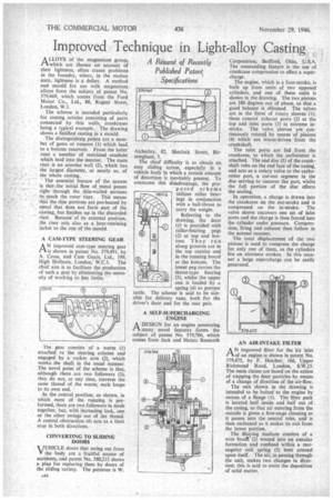
The scheme is intended particularly for casting articles consisting of parts connected by thin walls, crankcases being a typical example. The drawing shows a finished casting in a mould.
The distinguishing points are a number of gates or runners (1) which lead to a bottom reservoir. From the latter runs a number of restricted conduits which lead into the interior. The main riser is an annular wall (2), which has the largest diameter, or nearly so, of the whole casting.
The essential feature of the system is that the initial flow of metal passes right through the thin-walled sections to reach the outer riser. This means thin the thin portions are pre-heated by metal that does not form part of the casting, but finishes up in the discarded riser. Because of its external position, the riser acts also as a heat-retaining jacket to the rest of the mould.
A CAM-TYPE STEERING GEAR
ANimproved cam-type steering gear is shown in patent No. 579,491, by A. Cross, and Cam Gears, Ltd., 199, _High Holborn, London; W.C.1. The chief aim is to facilitate the production of such a gear by eliminating the necessity of working to fine limits.
The gear consists of a worm (I) attached to the steering column and engaged by a rocker arm (2), which works the shaft in the usual manner. The novel point of the scheme is that, although there are two followers (3), they do not, at any time, traverse the same thread of the worm; each keeps to its own end.
In the central position, as shown, in which most of the running is performed, there are two followers in mesh together, but, with increasing lock, one or the other swings out of the thread. A central obstruction (4) acts as a limit stop in both directions.
CONVERTING TO SLIDING DOORS VEHICLE doors that swing out from V the body are a fruitful source of accidents, and patent No. 580,212 shows a plan for replacing them by doors of the sliding variety. The patentee is W. Atcherley, 82, Sherlock Street, Birmingham, 5.
The chief difficulty is to obtain an easy sliding action, especially in a vehicle body in which a certain amount of distortion is inevitably present. To overcome this disadvantage, the proposed scheme utilizes roller bearings in conjunction with a ball-thrust to carry the weight.
Referring to the drawing, the door (1) is provided with roller-bearing pegs (2) at top and bottom. They run along grooves cut in the top cornice and in the running board at the bottom. The lower peg carries the thrust-type bearing (3), whilst the upper one is loaded by a spring (4) to prevent rattle. The scheme is said to be suitable for delivery vans, both for the driver's door and for the rear pair.
A SELF-SUPERCHARGING ENGINE
A DESIGN for an engine possessing many novel features forms the subject of patent No. 579,706, which comes from Jack and Heintz Research
Corporation, Bedford, Ohio, U,S.A.• The outstanding feature is the use of crankcase compression to effect a supercharge.
The engine, which is a four-stroke, is built up from units of two opposed cylinders, and one of these units is shown in the drawing. The two pistons are 180 degrees out of phase, so that a good balance is obtained. The valves are in the form of rotary sleeves (1); these control exhaust ports (2) at the top and inlet ports (3) at extreme instroke. The valve sleeves are continimusly rotated by means• of pinions (4) which are worm-driven from the crankshaft. • The inlet ports are fed from the crankcase, to which the carburetter is attached. The end disc (5) of the crankshaft rubs on the end face of the casing, and acts as a rotary valve to the carburetter port, a cut-out segment in the disc serving to uncover the port, whilst the full portion of the disc effects the sealing.
In operation, a charge is drawn into the crankcase on the out-stroke and is compressed on the in-stroke. The valve sleeve uncovers one set of inlet ports and the charge is then forced into the cylinder under pressure. Compression, firing and exhaust then follow in the normal manner.
The total displacement of the two pistons is used to compress the charge for only one of them, as the cylinders fire on alternate strokes. In this manner a large supercharge can be easily generated.
AN AIR-INTAKE FILTER
:AA N improved filter for the hir inlet
d an engine is shown in patent No. 579,475, by F. Heather, 166, Upper Richmond Road, London, S.W.I5. The main claims are based on the action of trapping the finer particles by means of a change of direction of the air-flow.
The unit shown in the drawing is intended to be bolted to the engine by means of a flange (.1). The filter pack is located half inside and half out of the casing, so that air entering from the outside is given a first-stage cleaning as it passes into the central tube, and is then recleaned as it makes its exit from the lower portion.
The filtering medium consists of a wire brust(2) wound into an annular formation and confined within a rectangular coil spring (3) bent around upon itself. The air, in passing through the unit, makes two changes in direction; this is said to assist the deposition of solid matter.