


These Problems Must
Page 52
Page 53
Page 54
If you've noticed an error in this article please click here to report it so we can fix it.
Iced in
DESIGNIN S TURBINES
By 3. PICKLES, A.M.IA.E.
TO discuss the design of a gas turbine small enough to be used in a road vehicle must, of course, be merely conjecture, but sufficient information has now been released concerning British and German turbine units to enable a good idea of the construction to be obtained, together with some of the service problems of large-sized machines. In many respects the small-scale version would differ. For instance, there would be no gain trom "ram" effect caused by passage through the air, and flexibility of power delivery would require to be much greater than that found on any aircraft turbine. There is, however, much that can be learned from units which are operating.
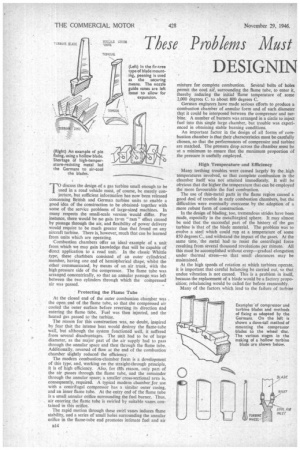
Combustion chambers offer an ideal example of a unit from which we may gain knowledge that will be capable of direct application to a road unit. In the classic Whittle type, these chathbers consisted of an outer cylindrical member, having one end of hemiepherical shape, whilst the other communicated, by means of an air trunk, with the high pressure side of the compressor. The flame tube was arranged concentrically, so that an annular passage was left between the two cylinders through which the compressed air was passed.
Protecting the Flame Tube At the closed end of the outer combustion chamber was the open end of the flame tube, so that the compressed air cooled the outer surface before reversing its direction and entering the flame tube. Fuel was then injected, and the heated gas passed to the turbine.
The reason for this construction was, no doubt, inspired by fear that the intense heat would destroy the flame-tube wall, but although the system functioned well, it suffered from several disadvantages. The unit had to be of large diameter, as the major part of the air supply had to pass _through the annular space and then through the flame tube. Additionally, reversal of flow at the end of the combustion chamber slightly reduced • the efficiency.
The modern combustion-chamber form is a development of this type, and, working on the straight-through principle, it is of high efficiency. Also, for thts reason, only part of the air passes through the flame tube, and the remainder through the annular space; a smaller cross-sectional area is, consequently, required. A typical modern chamber for use with a centrifugal compressor has a similar outer casing, and an inner flame tube. At the entry end of the flame tube is a small annular orifice surrounding the fuel burner. Thus, air entering the flame tube is swirled by suitable vanes contained in this orifice.
The rapid motion through these swirl vanes induces flame stability, and a series of small holes surrounding the annular orifice in the flame-tube end promotes intimate fuel and air
mixture for complete combustion. Several belts of holes permit the cool airl, surrounding the flame tube, to enter it, thereby reducing the initial 'flame temperature of some 2,000 degrees C. to about 800 degrees C.
German engineers have made serious efforts to produce a combustion chamber of annular form and of such diameter that it could be interposed between the compressor and turbine. A number of burners was arranged in a circle to inject fuel into this single large chamber, but trouble was experienced in obtaining stable burning conditions.
An imp-ortant factor in the design of all forms of combustion chamber is that their characteristics must be carefully chosen, so that the performances of compressor and turbine are matched. The pressure drop across the chamber must be at a minimum to ensure that the maximum proportion of the pressure is usefully employed.
High Temperature-and Efficiency Many teething troubles were caused largely by the .high -temperatures involved, so that complete combustion in the chamber itself was not attained immediately. It will be obvious that the higher the temperature that can be employed the more favourable the fuel combustion.
The use of thin-metal parts in the flame region caused a good deal of trouble in early combustion chambers, but the difficulties were eventually overcome by the adoption of a more robust form of construction.
In the design of blading, too, tremendous strides have been made, especially in the metallergical sphere. It may almost be said that the successful part of the history of the gas turbine is that of the blade material. The problem was to evolve a steel which could run at a temperature of some 850 degrees C., and withstand the impact of the gases. At the same time, the metal had to resist the centrifugal force resulting from several thousand revolutions per minute. All this must be accomplished without creep—gradual elongation under thermal stress—so that small clearances may be maintained.
At the high speeds of rotation at which turbines operate, it is important that careful balancing be carried out, so that undue vibration is not caused. This is a problem in itself, because the replacement of a blade would be a factory proposition; rebalancing would be called for before reassembly.
Many of the factors which lead to the failure of turbine
blades are now known and suitable steps have been taken-to eliminate this trouble. A breakdown from this source, on a road vehicle, would not merely immobilize the machine, but would, if some of the speeds suggested be employed, cause injury or even loss of life among persons in the area. The old trouble, of over-sharp corners, where the blade proper joins the root, was a common cause of failure, and was overcome by introducing more generous fillets.
Vibration troubles exist even in such inherently smooth machinery as turbines, although, in the case of a small unit, the difficulties associated with producing the components will probably result in very stiff sections being employed, and thus there may be little likelihood of trouble from this cause.
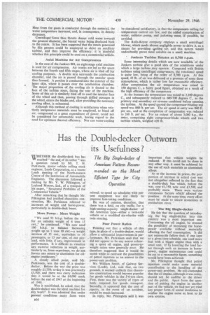
Blade construction, on the early B.M.W. turbines, was simple and ingenious. Two forgings were mated together and welded, the joint running longitudinally, and the whole was afterwards machined accurately to form. A later type was fabricated from steel sheet, but suffered from the disadvantage of having only a. quarter of the life of the former type; failure also occurred fairly rapidly. Nevertheless, the principle is attractive for mass production, and, after development, may offer possibilities in this direction.
Another economical method of blade manufacture employed a short length of tubing as a basis. One end was closed and the component was first pressed to form to give the correct profile. The lower end was then worked to leave a transverse hole and, slightly above this, a tapered shoulder
was formed on each side. A deep groove, cut in the periphery of the blade wheel, had tapered sides to match the angle of the shoulder, and -holes permitted a pin to be pressed through the hole in the blade, thus locking it securely. Further holes were drilled in the rotor, which communicated with the blade groove, this being cut specially deep for the purpose. Cool air was passed into the groove by way of the orifices, and thence to the hollow blades.
Pin Method of Blade Fixing For use in conjunction with the hollow blade. Junkers had another interesting method of blade fixing. The lower part of the rotor blade was approximately rectangular. Helical grooves were cut in the face of the wheel, so that tongues were formed, their shape being such that they matched the lower shape of the blade. With the blade in position, holes were drilled diagonally across the space, so that they entered one tongue and became an immovable fixture. Thus, each blade was held by two pins and could readily be assembled or removed.
Compressor blades on Junkers turbines were formed at the base with a somewhat wide foot with bevelled sides. The wheel was slotted to suit the shape of the blade foot, which, when slid axially into position, was held in the manner of a dovetail. Once in position, a hole was drilled half in the blade and half in the compressor wheel. This hole was then tapped to teceive a setscrew.
There being no need to use makeshift materials, British manufacturers were able to concentrate primarily on quality.
De Havilland has a method of blade fixing which is aptly described as of the "fir-tree-type " root. The periphery of the impellor wheel has broached axial slots, with serrations tapering towards the wheel centre. The blades have corresponding teeth cut on their roots, the shape being reminiscent of a fir tree. On assembly, the blades are slid axially into position and the wheel is peened to hold them in position. To resist thrust, a slightly heavier peening is used on the side remote from the fixed blades.
An interesting method of blade cooling, using a hollow form of construction, has been evolved by German engineers. The cooling water is contained in the revolving centre drum, and, through drillings, passes to the centre of the blades. Heat from the gases is conducted through the material, the water temperature increases, and, in consequence, its density decreases.
Centrifugal force thus thrusts denser cold water towards the greatest diameter, the heated water being displaced back to the centre. It has been suggested that the steam generated by this process could be employed to drive an auxiliary turbine, and thus improve the efficiency; it is doubtful whether this principle could be used on a commercial vehicle.
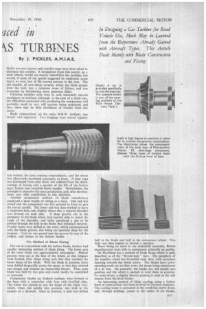
Axial Machine for Air Compression In the case of the Junkers 004, an eight-stage axial machine is used for air compression. Air trunks are led to the space between the fourth and fifth stages, where air is bled off for cooling purposes. A double skin surrounds the combustion chamber, and the air is passed through the annular space thus formed. A portion is conducted into the exterior of the inner skin, where it 'passes over the combustion chamber. • The major proportion of the cooling air is ducted to the face of the turbine rotor, facing the rear of the machine. Some of this au is similarly bled off to cool the interior face of the wheel and then, passing through drilled passages in the wheel, enters the blades and, after providing the necessary cooling effect, is exhausted.
Although this method of cooling is satisfactory when relatively inexpensive materials must be employed, to bleed off air, compressed at a great expenditure of power, could not be considered for automobile work, having regard to the need for optimum thermal efficiency. Nor can water-copling
be cOnsidered satisfactory, in that the components calling fortemperature control are few, and the added complication of water, radiator pump, and jacketing must, if possible, be avoided.
The Rolls-Royce company employs a small centrifugal blower, which needs almost negligible power to drive it, as a means for providing spoling air, and this system would undoubtedly prove most suitable on a small machine.
' Junkers Turbine Rotates at 8,700 r.p.m. •
Some interesting details which are now available-of the Junkers turbine give a good idea of the conditions under which a large turbine may operate. Compared with British turbines using centrifugal compressors, the rotational speed is quite low, being of the order of 8,700 r.p.m. At this speed, 43 lb. of air was delivered at a pressure of some three atmospheres, which is rather low for reasonable efficiency. After compression the air temperature was raised to 150 degrees C., a fairly good figure, obtained as a result of the high efficiency of the compressor,
At the burners the temperature was raised to 2,100 degrees C., and subsequently reduced to 600-700 degrees C., as the primary and secondary air streams combined before entering. the turbine. At the speed quoted the compressor-blading top speed was 860 ft. per sec. The air speed at entry was 860 ft. per sec.. and at the completion of compression was reduced to 260 ft. per sec. For an output of about 3,000 h.p., the rotor, comprising eight compressor-blade wheels and two turbine wheels, weighed 420 lb.