


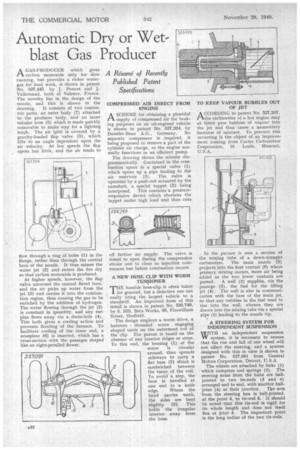
Automatic Dry or Wet blast Gas Producer
Page 34
If you've noticed an error in this article please click here to report it so we can fix it.
A Résumé of Recently Published Patent Specifications A GAS-PRODUCER which gives carbon monoxide only for sloW running, but provides a richer watergas for load work, is shown in patent No. 527,445, by J. Poncet and J. VaIlernaud, both of Valence, France. The novelty lies in the design of the nozzle, and this is shown in the drawing. It consists of two concentric parts, an outer body (7) attached to the producer body, and an inner tubular nose (5) which is made quickly removable to make way for a lighting torch. The air inlet is covered by a gravity-loaded flap valve (3), which lifts to an angle dependent upon the air velocity. At low speeds the flap opens but little, and the air tends to
flow through a ring of holes (I) in the flange, rather than through the central bore of the nozzle. It thus misses the water jet (2) and enters the fire dry so that carbon monoxide is produced.
At higher speeds, however, the flap valve uncovers the central flared bore, and the air picks up water from the jet (2) and carries it into the combustion region, thus causing the gas to be enriched by the addition of hydrogen. The water flowing through the jet (2) is constant in quantity, and any surplus flows away via a drain-hole (4). This both gives a cooling action and prevents flooding of the furnace. To facilitate cooling of the inner end, a nosepiece (6) is inserted, which has a cross-section with the passages shaped like an eight-petalled flower. COMPRESSED AIR DIRECT FROM ENGINE
ASCHEME for obtaining a plentiful supply of compressed air for braking purposes on an oil-engined vehicle is shown in patent No. 527,254, by Daimler-Benz A.G., Germany. No separate compressor is required, it being proposed to remove a part of the cylinder air charge, as the engine normally functions as an efficient pump.
The drawing shows the scheme diagrammatically. Contained in the combustion space is a special valve (1) which opens up a pipe leading to the air reservoir (3). The valve is operated by a push-rod actuated by the camshaft, a special tappet (2) being interposed. This contains a pressureresponsive device which shortens the tappet under high load and thus cuts off further air supply. The valve is timed to open during the compression stroke and to close as injection commences but before combustion occurs.
A NEW HOSE CLIP WITH WORM TENSIONER
Pri-IE humble hose-clip is often taken 1 for granted, but a defective one can easily bring the largest vehicle to a standstill. An improved form of this detail is shown in patent No. 526,749, by S. Hill, Beta Works, 66, Fitzwilliarn Street, Sheffield.
The design employs a worm drive, a buttress threaded screw engaging shaped teeth on the outermost coil of the clip. The patent is based on thn absence of any interior ridges or steps. To this end, the housing (1) of the screw is circular around, then spreads sideways to carry a flat base (2) Which is sandwiched between the turns of the coil. To avoid a step, the base is bevelled at one end to a knife edge. Where the band carries teeth, the sides are bent slightly (3). This holds the irregular interior away from the hose,
TO KEEP VAPOUR BUBBLES OUT OF JET
ACCORDING to patent No. 527,207, the carburetter of a hot engine may at times pass bubbles of vapour into the jet and thus cause a momentary leanness of mixture. To prevent this occurring is the object of an improvement coming from Carter Carburettor Corporation, St. Louis, Missouri, U.S. A.
In the picture is seen a section of the mixing tube of a down-draught carburetter. The main nozzle (5) projects into the first venturi (6) where primary mixing occurs, more air being added as the two lower venturis are passed. A well (2) supplies, via the passage (3), the fuel for the idling jet (4). The well is also in communication with the base of the main jet, so that any bubbles in the fuel tend to rise into the well, whence they are drawn into the mixing tube via a special pipe (1) leading to the nozzle tip.
A STEERING SYSTEM FOR INDEPENDENT SUSPENSION [WITH an independent suspension W system, it is necessary to ensure that the rise and fall of one wheel will not affect the steering, and a system designed with this in view is shown in patent No. 527,091 from General Motors Corporation, Detroit, U.S.A.
The wheels are attached by links (I) which compress coil springs (2). The steering arms from the hubs are balljointed to two tie-rods (3 and 6) arranged end to end, with another ball.
joint (4) at their junction. Tlae arm • from the steering box is ball-jointed. at the point 5, to tie-rod 6. It should be noted that this tie-rod is rigid for its whole length and does not itself flex at joint 5. The important point is the long radius of the two tie-rods.